- 您现在的位置:买卖IC网 > PDF目录1773 > A3981KLPTR-T (Allegro Microsystems Inc)IC MOTOR DVR MICROSTEP 28-TSSOP PDF资料下载
参数资料
| 型号: | A3981KLPTR-T |
| 厂商: | Allegro Microsystems Inc |
| 文件页数: | 26/43页 |
| 文件大小: | 0K |
| 描述: | IC MOTOR DVR MICROSTEP 28-TSSOP |
| 标准包装: | 1 |
| 系列: | * |
| 应用: | * |
| 输出数: | * |
| 电流 - 输出: | * |
| 电压 - 负载: | * |
| 电源电压: | * |
| 工作温度: | * |
| 安装类型: | 表面贴装 |
| 封装/外壳: | 28-SOIC(0.173",4.40mm 宽)裸露焊盘 |
| 供应商设备封装: | 28-TSSOP 裸露焊盘 |
| 包装: | 标准包装 |
| 其它名称: | 620-1458-6 |
第1页第2页第3页第4页第5页第6页第7页第8页第9页第10页第11页第12页第13页第14页第15页第16页第17页第18页第19页第20页第21页第22页第23页第24页第25页当前第26页第27页第28页第29页第30页第31页第32页第33页第34页第35页第36页第37页第38页第39页第40页第41页第42页第43页
�� �
�
�A3981�
�Automotive,� Programmable� Stepper� Driver�
�reference� value.� Although� the� current� in� Q3� and� Q4� for� phase� A� is�
�effectively� negative,� the� negation� is� provided� by� controlling� the�
�direction� of� the� current.� The� current� control� scheme� still� operates�
�using� positive� values.�
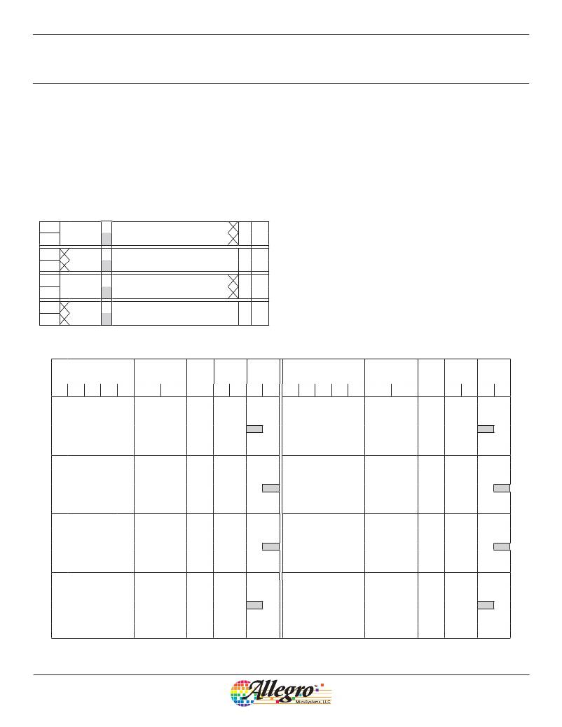
�As� shown� below,� the� table� of� values� can� be� extended� to� include�
�Q3� and� Q4� with� the� current� direction� indicated� in� the� last� column.�
�Note� that� the� same� value� is� now� applied� to� four� locations� in� the�
�full� 360-degree� electrical� cycle.�
�Shown� outlined� above,� steps� 4,� 28,� 36,� and� 60� all� contain� the�
�value� 23.�
�The� other� phase,� phase� B,� uses� the� same� values� as� phase� A� but�
�shifted� back� by� 16� Step� Angle� Numbers.� The� full� distribution� of�
�the� value� entered� in� step� 4� of� phase� A� is� highlighted� in� figure� 13�
�(and� shown� in� table� 7).� This� single� value� is� used� in� a� total� of� eight�
�locations.� The� same� distribution� of� values� applies� to� all� the� values�
�in� steps� 1� to� 15.� These� values� are� defined� in� the� A3981� as� PT(0)�
�to� PT(14),� respectively.�
�Step� 0�
�Value� 0�
�Step�
�Value�
�1� 2� 3� 4� 5� 6� 7� 8� 9� 10� 11� 12� 13� 14� 15�
�5� 11� 18� 23� 29� 35� 40� 44� 48� 52� 55� 58� 60� 62� 63�
�31� 30� 29� 28� 27� 26� 25� 24� 23� 22� 21� 20� 19� 18� 17� 16�
�5� 11� 18� 23� 29� 35� 40� 44� 48� 52� 55� 58� 60� 62� 63� 63�
�Q1� FWD�
�Q2� FWD�
�There� are� two� exceptions� to� this� data� distribution� principal.� These�
�are� the� zero� value� and� the� maximum� value:�
�?� The� values� in� phase� A� steps� 0� and� 32� and� phase� B� steps� 16� and�
�48� are� always� set� to� zero� and� cannot� be� programmed.�
�Step� 32� 33� 34� 35� 36� 37� 38� 39� 40� 41� 42� 43� 44� 45� 46� 47�
�Value� 0� 5� 11� 18� 23� 29� 35� 40� 44� 48� 52� 55� 58� 60� 62� 63�
�Step� 63� 62� 61� 60� 59� 58� 57� 56� 55� 54� 53� 52� 51� 50� 49� 48�
�Value� 5� 11� 18� 23� 29� 35� 40� 44� 48� 52� 55� 58� 60� 62� 63� 63�
�Q3� Rev�
�Q4� Rev�
�?� The� maximum� value,� PT(15),� is� distributed� to� only� two� Step�
�Angle� Numbers� in� each� phase.� These� are� the� points� in� the� cycle�
�where� the� peak� current� is� required,� namely� phase� A� steps� 16� and�
�48� and� phase� B� steps� 0� and� 32.�
�Table� 7.� Phase� Current� Table� (default,� power-on� content)�
�Phase� Current�
�Step�
�Phase� Current�
�Step�
�Step� Angle� Number�
�(%� of� I� PMAX� )�
�Angle�
�Phase�
�DAC�
�Step� Angle� Number�
�(%� of� I� PMAX� )�
�Angle�
�Phase�
�DAC�
�Full� 1/2�
�1/4�
�1/8� 1/16�
�A�
�B�
�A�
�B�
�A�
�B�
�Full� 1/2�
�1/4�
�1/8� 1/16�
�A�
�B�
�A�
�B�
�A�
�B�
�0�
�0�
�0�
�0�
�0.00� 100.00�
�0.0�
�0�
�0�
�0�
�63�
�4�
�8�
�16�
�32� 0.00� -100.00�
�180.0�
�0�
�1�
�0�
�63�
�1�
�9.38� 100.00�
�5.4�
�0�
�0�
�5�
�63�
�33� -9.38� -100.00�
�185.4�
�1�
�1�
�5�
�63�
�1�
�2�
�3�
�18.75� 98.44�
�29.69� 95.31�
�10.8�
�17.3�
�0�
�0�
�0�
�0�
�11�
�18�
�62�
�60�
�17�
�34� -18.75� -98.44�
�35� -29.69� -95.31�
�190.8�
�197.3�
�1�
�1�
�1�
�1�
�11�
�18�
�62�
�60�
�1�
�2�
�4�
�37.50� 92.19�
�22.1�
�0�
�0�
�23�
�58�
�9�
�18�
�36� -37.50� -92.19�
�202.1�
�1�
�1�
�23�
�58�
�5�
�46.88� 87.50�
�28.2�
�0�
�0�
�29�
�55�
�37� -46.88� -87.50�
�208.2�
�1�
�1�
�29�
�55�
�3�
�6�
�7�
�56.25� 82.81�
�64.06� 76.56�
�34.2�
�39.9�
�0�
�0�
�0�
�0�
�35�
�40�
�52�
�48�
�19�
�38� -56.25� -82.81�
�39� -64.06� -76.56�
�214.2�
�219.9�
�1�
�1�
�1�
�1�
�35�
�40�
�52�
�48�
�0�
�1�
�2�
�4�
�8�
�70.31� 70.31�
�45.0�
�0�
�0�
�44�
�44�
�2�
�5�
�10�
�20�
�40� -70.31� -70.31�
�225.0�
�1�
�1�
�44�
�44�
�9�
�76.56� 64.06�
�50.1�
�0�
�0�
�48�
�40�
�41� -76.56� -64.06�
�230.1�
�1�
�1�
�48�
�40�
�5�
�10�
�11�
�82.81� 56.25�
�87.50� 46.88�
�55.8�
�61.8�
�0�
�0�
�0�
�0�
�52�
�55�
�35�
�29�
�21�
�42� -82.81� -56.25�
�43� -87.50� -46.88�
�235.8�
�241.8�
�1�
�1�
�1�
�1�
�52�
�55�
�35�
�29�
�3�
�6�
�12�
�92.19� 37.50�
�67.9�
�0�
�0�
�58�
�23�
�11�
�22�
�44� -92.19� -37.50�
�247.9�
�1�
�1�
�58�
�23�
�13�
�95.31� 29.69�
�72.7�
�0�
�0�
�60�
�18�
�45� -95.31� -29.69�
�252.7�
�1�
�1�
�60�
�18�
�7�
�14�
�15�
�98.44� 18.75�
�100.00� 9.38�
�79.2�
�84.6�
�0�
�0�
�0�
�0�
�62�
�63�
�11�
�5�
�23�
�46� -98.44� -18.75�
�47� -100.00� -9.38�
�259.2�
�264.6�
�1�
�1�
�1�
�1�
�62�
�63�
�11�
�5�
�2�
�4�
�8�
�16�
�100.00� 0.00�
�90.0�
�0�
�0�
�63�
�0�
�6�
�12�
�24�
�48� -100.00� 0.00�
�270.0�
�1�
�1�
�63�
�0�
�17�
�100.00� -9.38�
�95.4�
�0�
�1�
�63�
�5�
�49� -100.00� 9.38�
�275.4�
�1�
�0�
�63�
�5�
�9�
�18�
�19�
�98.44� -18.75�
�95.31� -29.69�
�100.8�
�107.3�
�0�
�0�
�1�
�1�
�62�
�60�
�11�
�18�
�25�
�50� -98.44� 18.75�
�51� -95.31� 29.69�
�280.8�
�287.3�
�1�
�1�
�0�
�0�
�62�
�60�
�11�
�18�
�5�
�10�
�20�
�92.19� -37.50�
�112.1�
�0�
�1�
�58�
�23�
�13�
�26�
�52� -92.19� 37.50�
�292.1�
�1�
�0�
�58�
�23�
�21�
�87.50� -46.88�
�118.2�
�0�
�1�
�55�
�29�
�53� -87.50� 46.88�
�298.2�
�1�
�0�
�55�
�29�
�11�
�22�
�23�
�82.81� -56.25�
�76.56� -64.06�
�124.2�
�129.9�
�0�
�0�
�1�
�1�
�52�
�48�
�35�
�40�
�27�
�54� -82.81� 56.25�
�55� -76.56� 64.06�
�304.2�
�309.9�
�1�
�1�
�0�
�0�
�52�
�48�
�35�
�40�
�1�
�3�
�6�
�12�
�24�
�70.31� -70.31�
�135.0�
�0�
�1�
�44�
�44�
�3�
�7�
�14�
�28�
�56� -70.31� 70.31�
�315.0�
�1�
�0�
�44�
�44�
�25�
�64.06� -76.56�
�140.1�
�0�
�1�
�40�
�48�
�57� -64.06� 76.56�
�320.1�
�1�
�0�
�40�
�48�
�13�
�26�
�27�
�56.25� -82.81�
�46.88� -87.50�
�145.8�
�151.8�
�0�
�0�
�1�
�1�
�35�
�29�
�52�
�55�
�29�
�58� -56.25� 82.81�
�59� -46.88� 87.50�
�325.8�
�331.8�
�1�
�1�
�0�
�0�
�35�
�29�
�52�
�55�
�7�
�14�
�28�
�37.50� -92.19�
�157.9�
�0�
�1�
�23�
�58�
�15�
�30�
�60� -37.50� 92.19�
�337.9�
�1�
�0�
�23�
�58�
�29�
�29.69� -95.31�
�162.7�
�0�
�1�
�18�
�60�
�61� -29.69� 95.31�
�342.7�
�1�
�0�
�18�
�60�
�15�
�30�
�31�
�18.75� -98.44�
�9.38� -100.00�
�169.2�
�174.6�
�0�
�0�
�1�
�1�
�11�
�5�
�62�
�63�
�31�
�62� -18.75� 98.44�
�63� -9.38� 100.00�
�349.2�
�354.6�
�1�
�1�
�0�
�0�
�11�
�5�
�62�
�63�
�4�
�8�
�16�
�32�
�0.00� -100.00�
�180.0�
�0�
�1�
�0�
�63�
�0�
�0�
�0�
�0�
�0.00� 100.00�
�0.0�
�0�
�0�
�0�
�63�
�Allegro� MicroSystems,� LLC�
�115� Northeast� Cutoff�
�Worcester,� Massachusetts� 01615-0036� U.S.A.�
�1.508.853.5000;� www.allegromicro.com�
�26�
�相关PDF资料 |
PDF描述 |
|---|---|
| A3982SLB-T | IC MOTOR DRIVER STEPPER 24-SOIC |
| A3983SLP-T | IC MICRO STEPPING DRIVER 24-TSSO |
| A3984SLP-T | IC MICRO STEPPING DRIVER 24-TSSO |
| A3986SLDTR-T | IC DRIVER MICROSTEPPING 38-TSSOP |
| A3987SLPTR-T | IC DRIVER MICROSTEPPING 24-TSSOP |
相关代理商/技术参数 |
参数描述 |
|---|---|
| A3982 | 制造商:ALLEGRO 制造商全称:Allegro MicroSystems 功能描述:DMOS Stepper Motor Driver with Translator |
| A3982_13 | 制造商:ALLEGRO 制造商全称:Allegro MicroSystems 功能描述:DMOS Stepper Motor Driver with Translator |
| A3982SLB | 功能描述:IC MOTOR DRIVER STEPPER 24-SOIC RoHS:否 类别:集成电路 (IC) >> PMIC - 电机和风扇控制器,驱动器 系列:- 标准包装:1 系列:- 应用:直流电机驱动器,步进电机驱动器 评估套件:- 输出数:1 或 2 电流 - 输出:750mA 电压 - 负载:10 V ~ 40 V 电源电压:4.5 V ~ 5.5 V 工作温度:-20°C ~ 70°C 安装类型:表面贴装 封装/外壳:24-BFSOP(0.295",7.50mm 宽) 供应商设备封装:24-SOP 包装:Digi-Reel® 其它名称:MTS62C19A-HS105DKR |
| A3982SLB-T | 功能描述:IC MOTOR DRIVER STEPPER 24-SOIC RoHS:是 类别:集成电路 (IC) >> PMIC - 电机和风扇控制器,驱动器 系列:- 标准包装:1 系列:- 应用:直流电机驱动器,步进电机驱动器 评估套件:- 输出数:1 或 2 电流 - 输出:750mA 电压 - 负载:10 V ~ 40 V 电源电压:4.5 V ~ 5.5 V 工作温度:-20°C ~ 70°C 安装类型:表面贴装 封装/外壳:24-BFSOP(0.295",7.50mm 宽) 供应商设备封装:24-SOP 包装:Digi-Reel® 其它名称:MTS62C19A-HS105DKR |
| A3982SLB-T | 制造商:Allegro MicroSystems 功能描述:Motor Driver IC |
发布紧急采购,3分钟左右您将得到回复。