- 您现在的位置:买卖IC网 > PDF目录1773 > A3981KLPTR-T (Allegro Microsystems Inc)IC MOTOR DVR MICROSTEP 28-TSSOP PDF资料下载
参数资料
| 型号: | A3981KLPTR-T |
| 厂商: | Allegro Microsystems Inc |
| 文件页数: | 38/43页 |
| 文件大小: | 0K |
| 描述: | IC MOTOR DVR MICROSTEP 28-TSSOP |
| 标准包装: | 1 |
| 系列: | * |
| 应用: | * |
| 输出数: | * |
| 电流 - 输出: | * |
| 电压 - 负载: | * |
| 电源电压: | * |
| 工作温度: | * |
| 安装类型: | 表面贴装 |
| 封装/外壳: | 28-SOIC(0.173",4.40mm 宽)裸露焊盘 |
| 供应商设备封装: | 28-TSSOP 裸露焊盘 |
| 包装: | 标准包装 |
| 其它名称: | 620-1458-6 |
第1页第2页第3页第4页第5页第6页第7页第8页第9页第10页第11页第12页第13页第14页第15页第16页第17页第18页第19页第20页第21页第22页第23页第24页第25页第26页第27页第28页第29页第30页第31页第32页第33页第34页第35页第36页第37页当前第38页第39页第40页第41页第42页第43页
�� �
�
�A3981�
�Automotive,� Programmable� Stepper� Driver�
�in� the� first� instance,� by� the� resistance� of� the� winding� and� the�
�applied� voltage.�
�From� figure� A2(b)� it� is� also� apparent� that� varying� the� relative�
�current� in� each� phase� will� make� it� possible� to� move� the� rotor� to�
�any� intermediate� position� between� the� four� positions� of� figure� A1,�
�which� occur� when� only� a� single� phase� is� energized.� When� there� is�
�one� intermediate� position� this� is� known� as� half� step.� When� there�
�are� three� intermediate� positions� this� is� known� as� quarter� step�
�and� so� on.� Higher� resolution� microstepping� is� described� in� more�
�detail� below.�
�Phase� Current-Sequence� Diagrams�
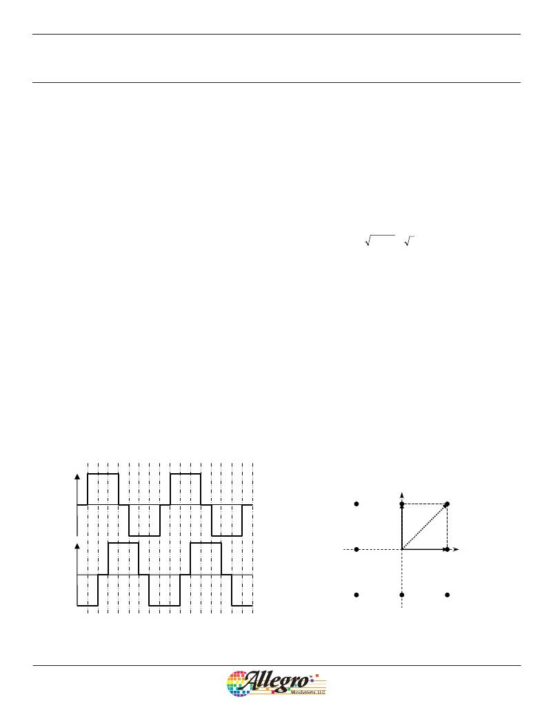
�Figure� A3� shows� the� full� sequence� of� the� two� phase� currents� illus-�
�trated� in� figure� A2.� This� shows� two� electrical� cycles,� equivalent� to�
�4� full� mechanical� steps� (8� half� steps).� The� full-step� positions� are�
�marked� F� and� the� half-step� positions� are� marked� H� .� Each� half� step�
�in� the� electrical� cycle� is� numbered,� from� 0� to� 7,� for� reference� later.�
�This� figure� shows� that,� when� discussing� stepper� motor� control,� it�
�is� necessary� to� know� the� relative� magnitude� and� direction� of� the�
�current� in� each� phase.� So,� rather� than� use� physical� representations�
�of� the� motor,� such� as� in� figure� A1� and� A2,� or� simple� time-based�
�current� waveforms,� such� as� figure� A3,� it� is� simpler� to� use� a� phase�
�diagram.� For� a� 2-pole� bipolar� motor� this� diagram� is� created� by�
�plotting� the� current� in� the� two� phases� as� orthogonal� vectors,� that�
�is,� as� vectors� at� 90°� to� each� other� as� shown� in� figure� A4.�
�Phase� Current-Phase� Diagrams�
�Figure� A4� shows� the� currents� of� figure� A3� plotted� on� a� phase�
�diagram� where� the� phase� A� current� is� represented� by� the� vertical�
�line� and� the� phase� B� current� by� the� horizontal� line.� The� half-step�
�numbers� correspond� to� the� numbers� in� figure� A3.� For� example,�
�at� step� 1� in� figure� A3,� the� phase� A� current� and� the� phase� B� cur-�
�rent� are� both� positive� and� with� the� same� magnitude.� These� two�
�currents� are� shown� in� figure� A4� as� the� two� solid� arrows.� Adding�
�these� two� current� vectors� together� gives� the� resultant� motor� cur-�
�rent� vector� indicated.� The� resultant� is� the� hypotenuse� of� a� right-�
�angled� triangle� with� the� two� other� sides� equal.� If� the� other� two�
�sides� are� assumed� to� be� 1� then� the� magnitude� of� the� hypotenuse�
�will� be:�
�1� 2� ?� 1� 2� ?� 2� ?� 1� .� 41�
�So� the� resultant� current� vector� will� be� 141%� of� the� value� of� the�
�current� in� phase� A� or� B,� positioned� at� 45°.�
�Torque� Ripple�
�Now,� the� torque� output� of� any� electrical� motor� is� directly� propor-�
�tional� to� the� magnitude� of� the� motor� current,� and� the� motor� cur-�
�rent� is� the� resultant� phase� current.� It� is� clear� from� figure� A4� that�
�the� resultant� phase� current� at� the� half-step� position� is� higher� than�
�the� current� at� the� full-step� position.� This� means� that� the� motor�
�torque� will� be� changing� as� the� motor� rotates,� resulting� in� what� is�
�known� as� torque� ripple� .� Torque� ripple� in� any� rotating� system� will�
�cause� mechanical� vibration� and� will� result� in� increased� audible�
�noise� and� possible� wear� on� other� mechanical� components.� Torque�
�ripple� can� be� reduced� by� ensuring� that� the� resultant� current� at� the�
�half-step� point� has� the� same� magnitude� as� the� full� current� in� the�
�single� phase� at� the� full-step� positions.�
�F�
�H�
�F�
�H�
�F�
�H�
�F�
�H�
�F�
�H�
�F�
�H�
�F�
�H�
�F�
�H�
�F�
�Phase� A�
�Phase�
�B�
�H�
�3�
�Current�
�2� F�
�1�
�H�
�Current�
�Resultant�
�Phase�
�A�
�Current�
�4�
�F�
�H�
�0�
�F�
�H�
�Phase� B�
�Current�
�5�
�6�
�F�
�7�
�6�
�7�
�0�
�1�
�2�
�3�
�4�
�5�
�6�
�7�
�0�
�1�
�2�
�3�
�4�
�5�
�6�
�Figure� A3.� Phase� current� sequence� for� uncompensated� half� step�
�Figure� A4.� Phase� diagram� for� uncompensated� half� step�
�Allegro� MicroSystems,� LLC�
�115� Northeast� Cutoff�
�Worcester,� Massachusetts� 01615-0036� U.S.A.�
�1.508.853.5000;� www.allegromicro.com�
�38�
�相关PDF资料 |
PDF描述 |
|---|---|
| A3982SLB-T | IC MOTOR DRIVER STEPPER 24-SOIC |
| A3983SLP-T | IC MICRO STEPPING DRIVER 24-TSSO |
| A3984SLP-T | IC MICRO STEPPING DRIVER 24-TSSO |
| A3986SLDTR-T | IC DRIVER MICROSTEPPING 38-TSSOP |
| A3987SLPTR-T | IC DRIVER MICROSTEPPING 24-TSSOP |
相关代理商/技术参数 |
参数描述 |
|---|---|
| A3982 | 制造商:ALLEGRO 制造商全称:Allegro MicroSystems 功能描述:DMOS Stepper Motor Driver with Translator |
| A3982_13 | 制造商:ALLEGRO 制造商全称:Allegro MicroSystems 功能描述:DMOS Stepper Motor Driver with Translator |
| A3982SLB | 功能描述:IC MOTOR DRIVER STEPPER 24-SOIC RoHS:否 类别:集成电路 (IC) >> PMIC - 电机和风扇控制器,驱动器 系列:- 标准包装:1 系列:- 应用:直流电机驱动器,步进电机驱动器 评估套件:- 输出数:1 或 2 电流 - 输出:750mA 电压 - 负载:10 V ~ 40 V 电源电压:4.5 V ~ 5.5 V 工作温度:-20°C ~ 70°C 安装类型:表面贴装 封装/外壳:24-BFSOP(0.295",7.50mm 宽) 供应商设备封装:24-SOP 包装:Digi-Reel® 其它名称:MTS62C19A-HS105DKR |
| A3982SLB-T | 功能描述:IC MOTOR DRIVER STEPPER 24-SOIC RoHS:是 类别:集成电路 (IC) >> PMIC - 电机和风扇控制器,驱动器 系列:- 标准包装:1 系列:- 应用:直流电机驱动器,步进电机驱动器 评估套件:- 输出数:1 或 2 电流 - 输出:750mA 电压 - 负载:10 V ~ 40 V 电源电压:4.5 V ~ 5.5 V 工作温度:-20°C ~ 70°C 安装类型:表面贴装 封装/外壳:24-BFSOP(0.295",7.50mm 宽) 供应商设备封装:24-SOP 包装:Digi-Reel® 其它名称:MTS62C19A-HS105DKR |
| A3982SLB-T | 制造商:Allegro MicroSystems 功能描述:Motor Driver IC |
发布紧急采购,3分钟左右您将得到回复。