- 您现在的位置:买卖IC网 > PDF目录1773 > A3981KLPTR-T (Allegro Microsystems Inc)IC MOTOR DVR MICROSTEP 28-TSSOP PDF资料下载
参数资料
| 型号: | A3981KLPTR-T |
| 厂商: | Allegro Microsystems Inc |
| 文件页数: | 30/43页 |
| 文件大小: | 0K |
| 描述: | IC MOTOR DVR MICROSTEP 28-TSSOP |
| 标准包装: | 1 |
| 系列: | * |
| 应用: | * |
| 输出数: | * |
| 电流 - 输出: | * |
| 电压 - 负载: | * |
| 电源电压: | * |
| 工作温度: | * |
| 安装类型: | 表面贴装 |
| 封装/外壳: | 28-SOIC(0.173",4.40mm 宽)裸露焊盘 |
| 供应商设备封装: | 28-TSSOP 裸露焊盘 |
| 包装: | 标准包装 |
| 其它名称: | 620-1458-6 |
第1页第2页第3页第4页第5页第6页第7页第8页第9页第10页第11页第12页第13页第14页第15页第16页第17页第18页第19页第20页第21页第22页第23页第24页第25页第26页第27页第28页第29页当前第30页第31页第32页第33页第34页第35页第36页第37页第38页第39页第40页第41页第42页第43页
�� �
�
�A3981�
�Automotive,� Programmable� Stepper� Driver�
�The� total� power� dissipation� for� each� of� the� four� decay� modes,�
�P� D(TOT)� XX� ,� is� the� average� power� for� the� drive� current� ramp� por-�
�tion,� P� D� ,� and� the� drive� current� decay� portion,� P� D(XX)� of� the� PWM�
�cycle.� For� slow� decay� the� current� will� be� rising� for� approximately�
�20%� of� the� cycle� and� decaying� for� approximately� 80%.� For� fast�
�decay� the� ratio� will� be� approximately� 50%.� Note� that� these� are�
�approximate� figures� and� will� vary� slightly� depending� on� the�
�motor� characteristics� and� the� use� of� synchronous� rectification.�
�The� following� formulas� may� be� used� to� estimate� total� power� dis-�
�sipation:�
�?� Synchronous� slow� decay� mode�
�P� D(TOT)SS� =� 0.2� � P� D� +� 0.8� � P� D(SS)�
�P� D(TOT)SS� =� 0.2� (� I� 2� [� R� DS(on)H� +� R� DS(on)L� ])� +� 0.8� (� I� 2� � 2� � R� DS(on)L� )�
�?� Non-synchronous� slow� decay� mode�
�P� D(TOT)NS� =� 0.2� � P� D� +� 0.8� � P� D(NS)�
�P� D(TOT)NS� =� 0.2� (� I� 2� [� R� DS(on)H� +� R� DS(on)L� ])� +� 0.8� (� I� 2� � R� DS(on)L� +� I� � V� F� )�
�5�
�4�
�3�
�2�
�?� Synchronous� fast� decay� mode�
�P� D(TOT)SF� =� 0.5� � P� D� +� 0.5� � P� D(SF)�
�P� D(TOT)SF� =� I� 2� (� R� DS(on)H� +� R� DS(on)L� )�
�?� Non-synchronous� fast� decay� mode�
�P� D(TOT)NF� =� 0.5� � P� D� +� 0.5� � P� D(NF)�
�P� D(TOT)NF� =� 0.5(� I� 2� [R� DS(on)H� +� R� DS(on)L� ]� )� +� 0.5(� I� � [� V� FH� +� V� FL� ]� )�
�An� approximation� of� the� total� dissipation� can� be� calculated� by�
�summing� the� total� power� dissipated� in� both� bridges� and� adding�
�the� control� circuit� power� due� to� V� BB� � I� BB� and� V� DD� � I� DD� .�
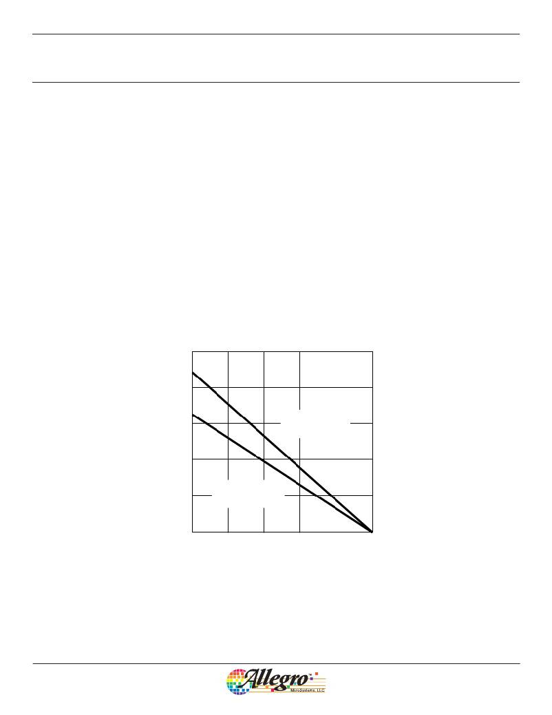
�The� total� power� at� the� required� ambient� temperature� can� then� be�
�compared� to� the� allowable� power� dissipation� shown� in� figure� 18.�
�For� critical� applications,� where� the� first� order� power� estimate� is�
�close� to� the� allowable� dissipation,� the� power� calculation� should�
�take� several� other� parameters� into� account� including:� motor�
�parameters,� dead� time,� and� switching� losses� in� the� controller.�
�R� θ� JA� =� 28� °C/W�
�(on� 4-layer� PCB)�
�1�
�R� θ� JA� =� 32� °C/W�
�(on� 2-layer� PCB)�
�0�
�25�
�50�
�75�
�100�
�125�
�150�
�Ambient� Temperature� (°C)�
�Figure� 18.� Allowable� power� dissipation,� on� typical� PCBs�
�Allegro� MicroSystems,� LLC�
�115� Northeast� Cutoff�
�Worcester,� Massachusetts� 01615-0036� U.S.A.�
�1.508.853.5000;� www.allegromicro.com�
�30�
�相关PDF资料 |
PDF描述 |
|---|---|
| A3982SLB-T | IC MOTOR DRIVER STEPPER 24-SOIC |
| A3983SLP-T | IC MICRO STEPPING DRIVER 24-TSSO |
| A3984SLP-T | IC MICRO STEPPING DRIVER 24-TSSO |
| A3986SLDTR-T | IC DRIVER MICROSTEPPING 38-TSSOP |
| A3987SLPTR-T | IC DRIVER MICROSTEPPING 24-TSSOP |
相关代理商/技术参数 |
参数描述 |
|---|---|
| A3982 | 制造商:ALLEGRO 制造商全称:Allegro MicroSystems 功能描述:DMOS Stepper Motor Driver with Translator |
| A3982_13 | 制造商:ALLEGRO 制造商全称:Allegro MicroSystems 功能描述:DMOS Stepper Motor Driver with Translator |
| A3982SLB | 功能描述:IC MOTOR DRIVER STEPPER 24-SOIC RoHS:否 类别:集成电路 (IC) >> PMIC - 电机和风扇控制器,驱动器 系列:- 标准包装:1 系列:- 应用:直流电机驱动器,步进电机驱动器 评估套件:- 输出数:1 或 2 电流 - 输出:750mA 电压 - 负载:10 V ~ 40 V 电源电压:4.5 V ~ 5.5 V 工作温度:-20°C ~ 70°C 安装类型:表面贴装 封装/外壳:24-BFSOP(0.295",7.50mm 宽) 供应商设备封装:24-SOP 包装:Digi-Reel® 其它名称:MTS62C19A-HS105DKR |
| A3982SLB-T | 功能描述:IC MOTOR DRIVER STEPPER 24-SOIC RoHS:是 类别:集成电路 (IC) >> PMIC - 电机和风扇控制器,驱动器 系列:- 标准包装:1 系列:- 应用:直流电机驱动器,步进电机驱动器 评估套件:- 输出数:1 或 2 电流 - 输出:750mA 电压 - 负载:10 V ~ 40 V 电源电压:4.5 V ~ 5.5 V 工作温度:-20°C ~ 70°C 安装类型:表面贴装 封装/外壳:24-BFSOP(0.295",7.50mm 宽) 供应商设备封装:24-SOP 包装:Digi-Reel® 其它名称:MTS62C19A-HS105DKR |
| A3982SLB-T | 制造商:Allegro MicroSystems 功能描述:Motor Driver IC |
发布紧急采购,3分钟左右您将得到回复。