- 您现在的位置:买卖IC网 > PDF目录1773 > A3981KLPTR-T (Allegro Microsystems Inc)IC MOTOR DVR MICROSTEP 28-TSSOP PDF资料下载
参数资料
| 型号: | A3981KLPTR-T |
| 厂商: | Allegro Microsystems Inc |
| 文件页数: | 37/43页 |
| 文件大小: | 0K |
| 描述: | IC MOTOR DVR MICROSTEP 28-TSSOP |
| 标准包装: | 1 |
| 系列: | * |
| 应用: | * |
| 输出数: | * |
| 电流 - 输出: | * |
| 电压 - 负载: | * |
| 电源电压: | * |
| 工作温度: | * |
| 安装类型: | 表面贴装 |
| 封装/外壳: | 28-SOIC(0.173",4.40mm 宽)裸露焊盘 |
| 供应商设备封装: | 28-TSSOP 裸露焊盘 |
| 包装: | 标准包装 |
| 其它名称: | 620-1458-6 |
第1页第2页第3页第4页第5页第6页第7页第8页第9页第10页第11页第12页第13页第14页第15页第16页第17页第18页第19页第20页第21页第22页第23页第24页第25页第26页第27页第28页第29页第30页第31页第32页第33页第34页第35页第36页当前第37页第38页第39页第40页第41页第42页第43页
�� �
�
�A3981�
�Automotive,� Programmable� Stepper� Driver�
�In� the� next� panel,� panel� (b),� the� current� is� flowing� down� through�
�the� phase� B� winding� from� top� to� bottom� and� there� is� no� current�
�in� phase� A.� The� result� is� an� N� pole� on� the� B� electromagnets� and�
�an� S� pole� on� the� B-bar� electromagnets.� These� magnetic� poles� will�
�attract� and� repel� the� permanent� magnets� on� the� rotor� producing� a�
�force� that� moves� the� rotor� from� left� to� right� in� the� diagram� until�
�the� poles� of� the� permanent� magnets� again� align� with� the� poles� of�
�the� electromagnets.�
�In� panel� (c),� the� current� is� flowing� up� through� the� phase� A� wind-�
�ing� from� bottom� to� top� and� there� is� no� current� in� phase� B.� This�
�reverses� the� pole� orientation� from� the� top� panel,� such� that� there�
�is� an� S� pole� on� the� A� electromagnets� and� an� N� pole� on� the� A-bar�
�electromagnets.� As� before,� these� magnetic� poles� will� attract� and�
�repel� the� permanent� magnets� on� the� rotor� producing� a� force� that�
�moves� the� rotor� from� left� to� right� in� the� diagram,� until� poles� of�
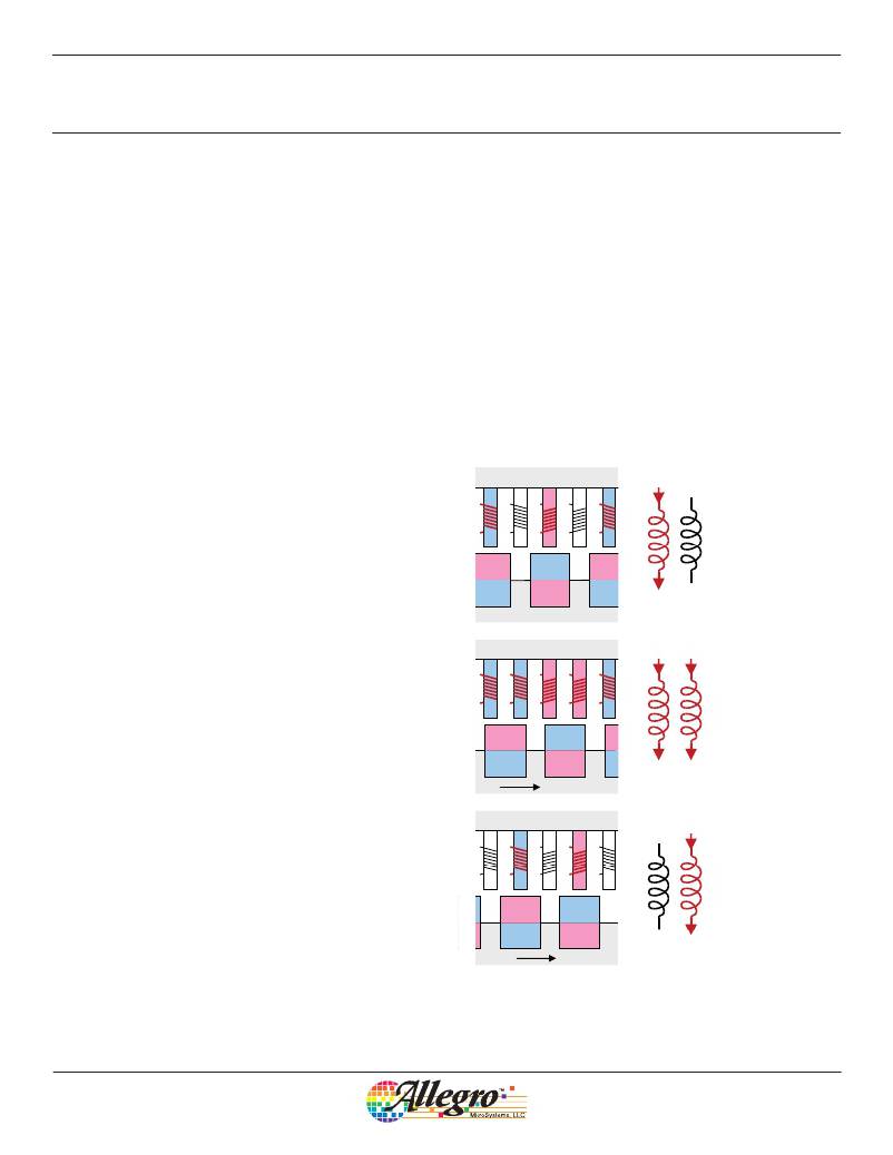
�Figure� A2� shows� the� basic� principle� of� microstepping.� Panels� (a)�
�and� (c)� of� figure� A2� correspond� to� panels� (a)� and� (b)� of� figure�
�A1.� Panel� (b)� shows� each� phase� energized� such� that� there� are� now�
�two� adjacent� N� poles� and� two� adjacent� S� poles.� In� this� example�
�the� currents� in� both� phases� is� the� same,� and� so� the� S� and� N� poles�
�of� the� rotor� now� move� to� half� way� between� the� positions� in�
�diagrams� (a)� and� (c).� Figure� A2� only� shows� a� single� mechanical�
�step� in� total,� which� is� one� quarter� of� a� full� electrical� cycle.� This�
�sequence� is� the� lowest� resolution� form� of� microstepping,� known�
�as� half� step� ,� and� is� the� simplest� method� of� driving� a� stepper� motor�
�in� half-step� mode.�
�The� currents� are� switched-on� in� the� correct� direction� in� sequence�
�and� no� current� control� is� required.� The� current� is� simply� defined,�
�the� permanent� magnets� again� align� with� the� poles� of� the� electro-�
�magnets.�
�A�
�B�
�Stator�
�_�
�A�
�_�
�B�
�A�
�The� bottom� panel,� panel� (d),� shows� the� final� combination� with�
�current� flowing� up� through� the� phase� B� winding� from� bottom� to�
�top� and� there� is� no� current� in� phase� A.� This� produces� an� N� pole�
�on� the� B� electromagnets� and� a� S� pole� on� the� B-bar� electromag-�
�N�
�S�
�S�
�N�
�N�
�S�
�A�
�B�
�(a)� Same� as�
�figure� A1(a)�
�nets.� As� before,� these� magnetic� poles� will� attract� and� repel� the�
�permanent� magnets� on� the� rotor� producing� a� force� that� moves� the�
�rotor� from� left� to� right� until� poles� of� the� permanent� magnets� again�
�align� with� the� poles� of� the� electromagnets.�
�N�
�S�
�Rotor�
�Stator�
�_�
�_�
�N�
�Each� of� the� four� steps� in� figure� A1� represents� a� single� full�
�A�
�B�
�A�
�B�
�A�
�mechanical� step� of� the� stepper� motor.� The� four� steps� together�
�represent� a� single� electrical� cycle.�
�N�
�N�
�S�
�S�
�N�
�A�
�B�
�(b)� Half-step�
�position�
�The� step� resolution� depends� entirely� on� the� mechanical� construc-�
�S�
�N�
�S�
�tion� of� the� motor� and� typically� there� will� be� 200� or� more� full�
�steps� per� mechanical� revolution� of� the� motor.� A� 200-step� motor�
�will� provide� a� resolution� of� 360� /� 200� =� 1.8°� of� rotation� per� step.�
�N�
�S�
�Rotor�
�N�
�Stepping� in� the� opposite� direction� to� that� described� above� is� sim-�
�ply� a� case� of� changing� the� step� sequence� or� inverting� one� of� the�
�phase� current� directions.�
�A�
�B�
�Stator�
�_�
�A�
�_�
�B�
�A�
�Microstepping�
�In� many� applications� it� is� necessary� to� improve� the� resolution� of�
�N�
�N�
�S�
�S�
�N�
�A�
�B�
�(c)� Same� as�
�figure� A1(b)�
�the� stepper� motor,� for� more� precise� positioning� control,� or� simply�
�to� increase� the� number� of� steps� per� revolution� to� reduce� the�
�torque� ripple� and� therefore� the� vibration� and� noise� of� the� motor.�
�Fortunately� this� can� be� achieved� by� driving� both� phases� at� the�
�same� time� in� order� to� move� the� rotor� to� a� position� between� two�
�N�
�S�
�Rotor�
�electromagnets.� This� is� known� generically� as� microstepping.�
�Figure� A2.� Half� step� operation�
�Allegro� MicroSystems,� LLC�
�115� Northeast� Cutoff�
�Worcester,� Massachusetts� 01615-0036� U.S.A.�
�1.508.853.5000;� www.allegromicro.com�
�37�
�相关PDF资料 |
PDF描述 |
|---|---|
| A3982SLB-T | IC MOTOR DRIVER STEPPER 24-SOIC |
| A3983SLP-T | IC MICRO STEPPING DRIVER 24-TSSO |
| A3984SLP-T | IC MICRO STEPPING DRIVER 24-TSSO |
| A3986SLDTR-T | IC DRIVER MICROSTEPPING 38-TSSOP |
| A3987SLPTR-T | IC DRIVER MICROSTEPPING 24-TSSOP |
相关代理商/技术参数 |
参数描述 |
|---|---|
| A3982 | 制造商:ALLEGRO 制造商全称:Allegro MicroSystems 功能描述:DMOS Stepper Motor Driver with Translator |
| A3982_13 | 制造商:ALLEGRO 制造商全称:Allegro MicroSystems 功能描述:DMOS Stepper Motor Driver with Translator |
| A3982SLB | 功能描述:IC MOTOR DRIVER STEPPER 24-SOIC RoHS:否 类别:集成电路 (IC) >> PMIC - 电机和风扇控制器,驱动器 系列:- 标准包装:1 系列:- 应用:直流电机驱动器,步进电机驱动器 评估套件:- 输出数:1 或 2 电流 - 输出:750mA 电压 - 负载:10 V ~ 40 V 电源电压:4.5 V ~ 5.5 V 工作温度:-20°C ~ 70°C 安装类型:表面贴装 封装/外壳:24-BFSOP(0.295",7.50mm 宽) 供应商设备封装:24-SOP 包装:Digi-Reel® 其它名称:MTS62C19A-HS105DKR |
| A3982SLB-T | 功能描述:IC MOTOR DRIVER STEPPER 24-SOIC RoHS:是 类别:集成电路 (IC) >> PMIC - 电机和风扇控制器,驱动器 系列:- 标准包装:1 系列:- 应用:直流电机驱动器,步进电机驱动器 评估套件:- 输出数:1 或 2 电流 - 输出:750mA 电压 - 负载:10 V ~ 40 V 电源电压:4.5 V ~ 5.5 V 工作温度:-20°C ~ 70°C 安装类型:表面贴装 封装/外壳:24-BFSOP(0.295",7.50mm 宽) 供应商设备封装:24-SOP 包装:Digi-Reel® 其它名称:MTS62C19A-HS105DKR |
| A3982SLB-T | 制造商:Allegro MicroSystems 功能描述:Motor Driver IC |
发布紧急采购,3分钟左右您将得到回复。