参数资料
| 型号: | ACS8946T |
| 厂商: | Semtech |
| 文件页数: | 38/40页 |
| 文件大小: | 0K |
| 描述: | IC JITTER ATT MULT PLL 48-QFN |
| 标准包装: | 1 |
| 类型: | 时钟/频率发生器,多路复用器 |
| PLL: | 是 |
| 主要目的: | 以太网,SONET/SDH |
| 输入: | LVPECL |
| 输出: | CML,LVPECL |
| 电路数: | 1 |
| 比率 - 输入:输出: | 2:4 |
| 差分 - 输入:输出: | 是/是 |
| 频率 - 最大: | 625MHz |
| 电源电压: | 3.135 V ~ 3.465 V |
| 工作温度: | -40°C ~ 85°C |
| 安装类型: | 表面贴装 |
| 封装/外壳: | 48-VFQFN 裸露焊盘 |
| 供应商设备封装: | 48-QFN(7x7) |
| 包装: | 托盘 |
第1页第2页第3页第4页第5页第6页第7页第8页第9页第10页第11页第12页第13页第14页第15页第16页第17页第18页第19页第20页第21页第22页第23页第24页第25页第26页第27页第28页第29页第30页第31页第32页第33页第34页第35页第36页第37页当前第38页第39页第40页
ADVANCED COMMUNICATIONS
FINAL
DATASHEET
Revision 3/November 2006 Semtech Corp.
Page 7
www.semtech.com
ACS8946 JAM PLL
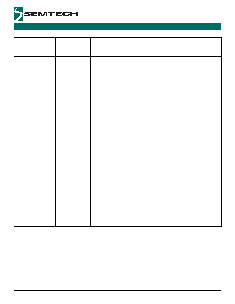
Note...A= Analog, I = Input, O = Output, P = Power, LVTTL/LVCMOSU = LVTTL/LVCMOS input with pull-up resistor, LVTTL/LVCMOSD =
LVTTL/LVCMOS input with pull-down resistor.
33
AUTO_SEL
I
LVTTL/
LVCMOSD
Used in combination with pin 32, SEL_CLK2, to select automatic switching mode, as
described in Table 4.
35
VCP
A
Analog
Connection for external loop filter components. This is the differential control voltage
input to the internal VCO and the internal differential charge pump output up to a level of
210
A.
36
VCN
A
Analog
Connection for external loop filter components. This is the differential control voltage
input to the internal VCO and the internal differential charge pump output up to a level of
210
A.
40
RESETB
I
LVTTL/
LVCMOSU
Schmitt
Trigger
Active low reset signal with pull up and Schmitt type input. Used to apply an active-low
Power-on Reset (POR) signal during system initialization. Should be connected via a
capacitor to ground.
41
SYNCP
I
LVPECL
Additional differential input (2 kHz or 8 kHz) where the Sync signal on this input is
sampled and resynchronized by clock output OUT1. The resynchronization can be
configured via CFG_IN4 and CFG_IN5 to be with the rising or falling edge of output OUT1;
see Table 12. Will also accept CML or LVDS signal types when used in conjunction with
42
SYNCN
I
LVPECL
Additional differential input (2 kHz or 8 kHz) where the Sync signal on this input is
sampled and resynchronized by clock output OUT1. The resynchronization can be
configured via CFG_IN4 and CFG_IN5 to be with the rising or falling edge of output OUT1;
see Table 12. Will also accept CML or LVDS signal types when used in conjunction with
44
SYNC_OUT
O
LVTTL/
LVCMOS
A sampled and therefore lower jitter and resynchronized version of the SYNC signal
selected from the SYNC1 input. The clock selected on OUT1 (see pins 2 and 3) is used to
perform the resynchronization. The resynchronization can be configured to be with the
rising or falling edge of output OUT1; see Table 12. The maximum output frequency on
OUT1 = 77.76 MHz when the Sync function is used.
45
RATE2A
I
LVTTL/
LVCMOSD
Inputs to control the frequency of the signal produced on pins 5 (OUT2P) and 6 (OUT2N).
See Table 11.
46
RATE2B
I
LVTTL/
LVCMOSD
Inputs to control the frequency of signal that is produced on pins 5 (OUT2P) and 6
(OUT2N). See Table 11.
47
RATE1A
I
LVTTL/
LVCMOSD
Inputs to control the frequency of signal that is produced on pins 2 (OUT1P) and 3
(OUT1N). See Table 11.
48
RATE1B
I
LVTTL/
LVCMOSD
Inputs to control the frequency of signal that is produced on pins 2 (OUT1P) and 3
(OUT1N). See Table 11.
Table 3 Functional Pins (cont...)
Pin No.
Symbol
I/O
Type
Description
相关PDF资料 |
PDF描述 |
|---|---|
| ACS8947T | IC JITTER ATT MULT PLL 48-QFN |
| AD10200BZ | IC ADC DUAL 12BIT 68-CLCC |
| AD10242BZ | IC ADC DUAL 12BIT 68-CLCC |
| AD10465BZ | IC ADC DUAL 14BIT 68-CLCC |
| AD13280AZ | IC ADC 12BIT 68CLCC |
相关代理商/技术参数 |
参数描述 |
|---|---|
| ACS8947T | 功能描述:IC JITTER ATT MULT PLL 48-QFN RoHS:是 类别:集成电路 (IC) >> 时钟/计时 - 专用 系列:- 标准包装:1,500 系列:- 类型:时钟缓冲器/驱动器 PLL:是 主要目的:- 输入:- 输出:- 电路数:- 比率 - 输入:输出:- 差分 - 输入:输出:- 频率 - 最大:- 电源电压:3.3V 工作温度:0°C ~ 70°C 安装类型:表面贴装 封装/外壳:28-SSOP(0.209",5.30mm 宽) 供应商设备封装:28-SSOP 包装:带卷 (TR) 其它名称:93786AFT |
| ACS9010 | 制造商:未知厂家 制造商全称:未知厂家 功能描述:Optoelectronic |
| ACS9510/50EVB | 制造商:Semtech Corporation 功能描述: |
| ACS9510EVB | 功能描述:EVALUATION BOARD FOR ACS9510 RoHS:是 类别:编程器,开发系统 >> 评估演示板和套件 系列:ToPSync™ 标准包装:1 系列:PCI Express® (PCIe) 主要目的:接口,收发器,PCI Express 嵌入式:- 已用 IC / 零件:DS80PCI800 主要属性:- 次要属性:- 已供物品:板 |
| ACS9510T | 制造商:Semtech Corporation 功能描述: |
发布紧急采购,3分钟左右您将得到回复。