- 您现在的位置:买卖IC网 > PDF目录1980 > AD73322LARUZ-REEL (Analog Devices Inc)IC PROCESSOR FRONTEND DL 28TSSOP PDF资料下载
参数资料
| 型号: | AD73322LARUZ-REEL |
| 厂商: | Analog Devices Inc |
| 文件页数: | 26/43页 |
| 文件大小: | 0K |
| 描述: | IC PROCESSOR FRONTEND DL 28TSSOP |
| 标准包装: | 2,500 |
| 位数: | 16 |
| 通道数: | 4 |
| 功率(瓦特): | 73mW |
| 电压 - 电源,模拟: | 2.7 V ~ 5.5 V |
| 电压 - 电源,数字: | 2.7 V ~ 5.5 V |
| 封装/外壳: | 28-TSSOP(0.173",4.40mm 宽) |
| 供应商设备封装: | 28-TSSOP |
| 包装: | 带卷 (TR) |
第1页第2页第3页第4页第5页第6页第7页第8页第9页第10页第11页第12页第13页第14页第15页第16页第17页第18页第19页第20页第21页第22页第23页第24页第25页当前第26页第27页第28页第29页第30页第31页第32页第33页第34页第35页第36页第37页第38页第39页第40页第41页第42页第43页
AD73322
–32–
REV. B
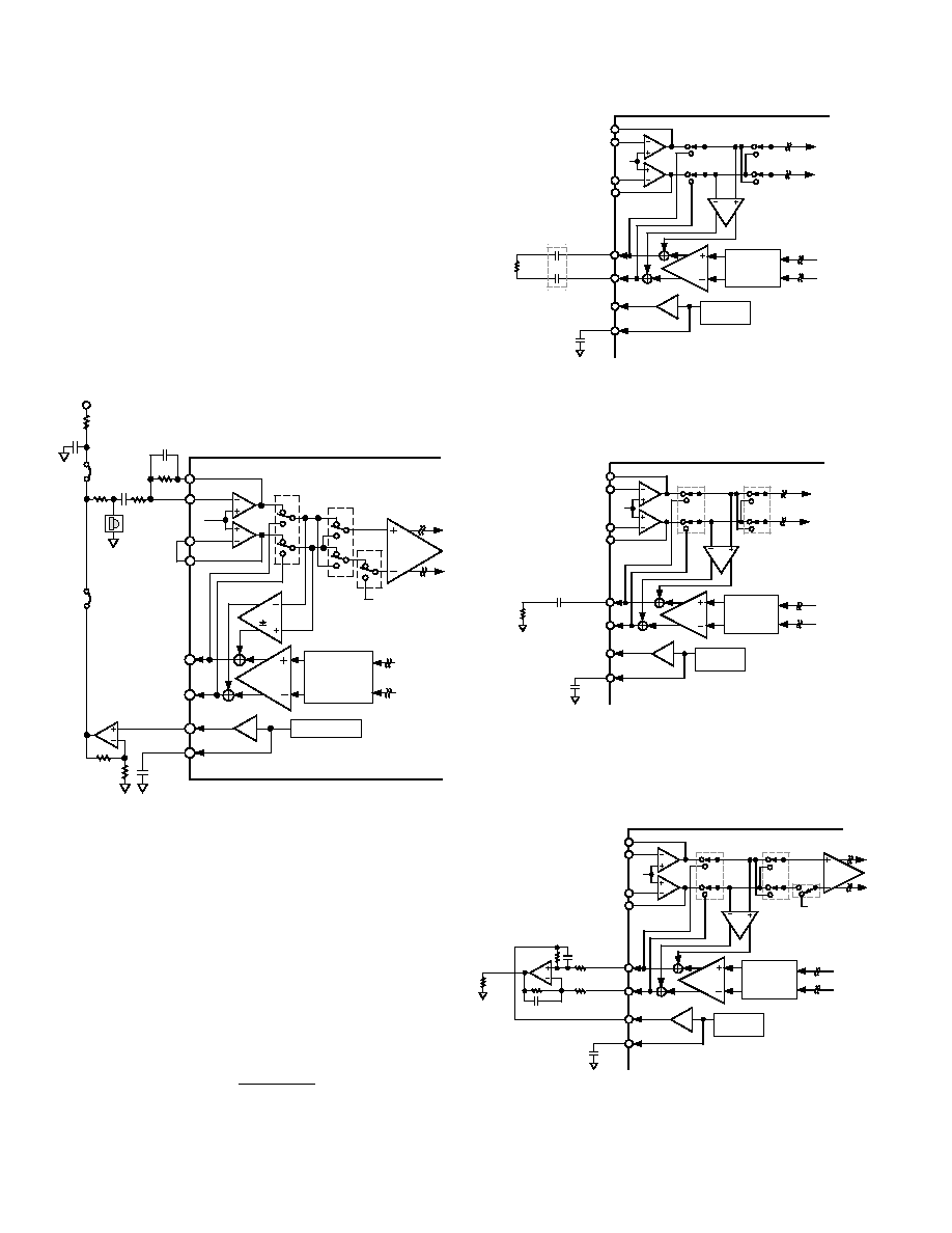
Interfacing to an Electret Microphone
Figure 34 details an interface for an electret microphone which
may be used in some voice applications. Electret microphones
typically feature a FET amplifier whose output is accessed on
the same lead which supplies power to the microphone, there-
fore this output signal must be capacitively coupled to remove
the power supply (dc) component. In this circuit the AD73322
input channel is being used in single-ended mode where the
internal inverting amplifier provides suitable gain to scale the
input signal relative to the ADC’s full-scale input range. The
buffered internal reference level at REFOUT is used via an
external buffer to provide power to the electret microphone.
This provides a quiet, stable supply for the microphone. If this
is not a concern, then the microphone can be powered from the
system power supply.
CONTINUOUS
TIME
LOW-PASS
FILTER
VREF
VFBN1
VINN1
VINP1
VFBP1
VOUTP1
VOUTN1
REFCAP
REFOUT
AD73322
VREF
+6/–15dB
PGA
REFERENCE
0/38dB
PGA
GAIN
1
C1
R2
R1
C2
RB
RA
+5V
ELECTRET
PROBE
10 F
CREFCAP
Figure 34. Electret Microphone Interface Circuit
Analog Output
The AD73322’s differential analog output (VOUT) is produced
by an on-chip differential amplifier. The differential output can
be ac-coupled or dc-coupled directly to a load which can be a
headset or the input of an external amplifier (the specified mini-
mum resistive load on the output section is 150
.) It is possible
to connect the outputs in either a differential or a single-ended
configuration but please note that the effective maximum output
voltage swing (peak to peak) is halved in the case of single-
ended connection. Figure 35 shows a simple circuit providing a
differential output with ac coupling. The capacitors in this cir-
cuit (COUT) are optional; if used, their value can be chosen as
follows:
C
fR
OUT
C
LOAD
=
1
2
π
where fC = desired cutoff frequency.
VFBN1
GAIN
1
VREF
VINN1
VINP1
VFBP1
VOUTP1
VOUTN1
REFCAP
REFOUT
REFERENCE
AD73322
CREFCAP
RLOAD
COUT
+6/–15dB
PGA
CONTINUOUS
TIME
LOW-PASS
FILTER
Figure 35. Example Circuit for Differential Output
Figure 36 shows an example circuit for providing a single-ended
output with ac coupling. The capacitor of this circuit (COUT) is
not optional if dc current drain is to be avoided.
VFBN1
GAIN
1
VREF
VINN1
VINP1
VFBP1
VOUTP1
VOUTN1
REFCAP
REFOUT
REFERENCE
AD73322
RLOAD
COUT
0.1 F
+6/–15dB
PGA
CONTINUOUS
TIME
LOW-PASS
FILTER
Figure 36. Example Circuit for Single-Ended Output
Differential to Single-Ended Output
In some applications it may be desireable to convert the full
differential output of the decoder channel to a single-ended
signal. The circuit of Figure 37 shows a scheme for doing this.
VFBN1
GAIN
1
VREF
VINN1
VINP1
VFBP1
VOUTP1
VOUTN1
REFCAP
REFOUT
REFERENCE
AD73322
VREF
0/38dB
PGA
RLOAD
R I
R F
0.1 F
+6/–15dB
PGA
CONTINUOUS
TIME
LOW-PASS
FILTER
Figure 37. Example Circuit for Differential to Single-
Ended Output Conversion
相关PDF资料 |
PDF描述 |
|---|---|
| AD73322LYRZ | IC ANALOG FRONT END DUAL 28-SOIC |
| AD73360ARZ | IC PROCESSOR FRONTEND 6CH 28SOIC |
| AD7352YRUZ-500RL7 | IC ADC DUAL 12BIT 3MSPS 16TSSOP |
| AD7356YRUZ-500RL7 | IC ADC DUAL 12BIT 5MSPS 16TSSOP |
| AD7357YRUZ | IC ADC DUAL14BIT 4.2MSPS 16TSSOP |
相关代理商/技术参数 |
参数描述 |
|---|---|
| AD73322LARZ | 功能描述:IC ANALOG FRONT END DUAL 28-SOIC RoHS:是 类别:集成电路 (IC) >> 数据采集 - 模拟前端 (AFE) 系列:- 产品培训模块:Lead (SnPb) Finish for COTS Obsolescence Mitigation Program 标准包装:2,500 系列:- 位数:- 通道数:2 功率(瓦特):- 电压 - 电源,模拟:3 V ~ 3.6 V 电压 - 电源,数字:3 V ~ 3.6 V 封装/外壳:32-VFQFN 裸露焊盘 供应商设备封装:32-QFN(5x5) 包装:带卷 (TR) |
| AD73322LARZ-REEL | 制造商:Analog Devices 功能描述:DUAL-CHANNEL, 3 V FRONT-END PROCESSOR FOR GENERAL PURPOSE - Tape and Reel |
| AD73322LAST | 制造商:Rochester Electronics LLC 功能描述:SPEECH AND TELEPHONY CODEC I.C. - Tape and Reel 制造商:Analog Devices 功能描述: |
| AD73322LAST-REEL | 制造商:Analog Devices 功能描述:Audio Codec 2ADC / 2DAC 16-Bit 44-Pin LQFP T/R 制造商:Rochester Electronics LLC 功能描述:SPEECH AND TELEPHONY CODEC I.C. - Tape and Reel |
| AD73322LASTZ | 制造商:Analog Devices 功能描述: 制造商:Rochester Electronics LLC 功能描述: |
发布紧急采购,3分钟左右您将得到回复。