参数资料
| 型号: | AD9146BCPZ |
| 厂商: | Analog Devices Inc |
| 文件页数: | 14/56页 |
| 文件大小: | 0K |
| 描述: | IC DAC 16BIT SRL DUAL 48LFCSP |
| 标准包装: | 1 |
| 系列: | TxDAC+® |
| 设置时间: | 20ns |
| 位数: | 16 |
| 数据接口: | 串行 |
| 转换器数目: | 2 |
| 电压电源: | 模拟和数字 |
| 工作温度: | -40°C ~ 85°C |
| 安装类型: | 表面贴装 |
| 封装/外壳: | 48-WFQFN 裸露焊盘,CSP |
| 供应商设备封装: | 48-LFCSP-WQ(7x7) |
| 包装: | 托盘 |
| 输出数目和类型: | 2 电流,单极 |
| 采样率(每秒): | 1.23G |
第1页第2页第3页第4页第5页第6页第7页第8页第9页第10页第11页第12页第13页当前第14页第15页第16页第17页第18页第19页第20页第21页第22页第23页第24页第25页第26页第27页第28页第29页第30页第31页第32页第33页第34页第35页第36页第37页第38页第39页第40页第41页第42页第43页第44页第45页第46页第47页第48页第49页第50页第51页第52页第53页第54页第55页第56页
Data Sheet
AD9146
Rev. A | Page 21 of 56
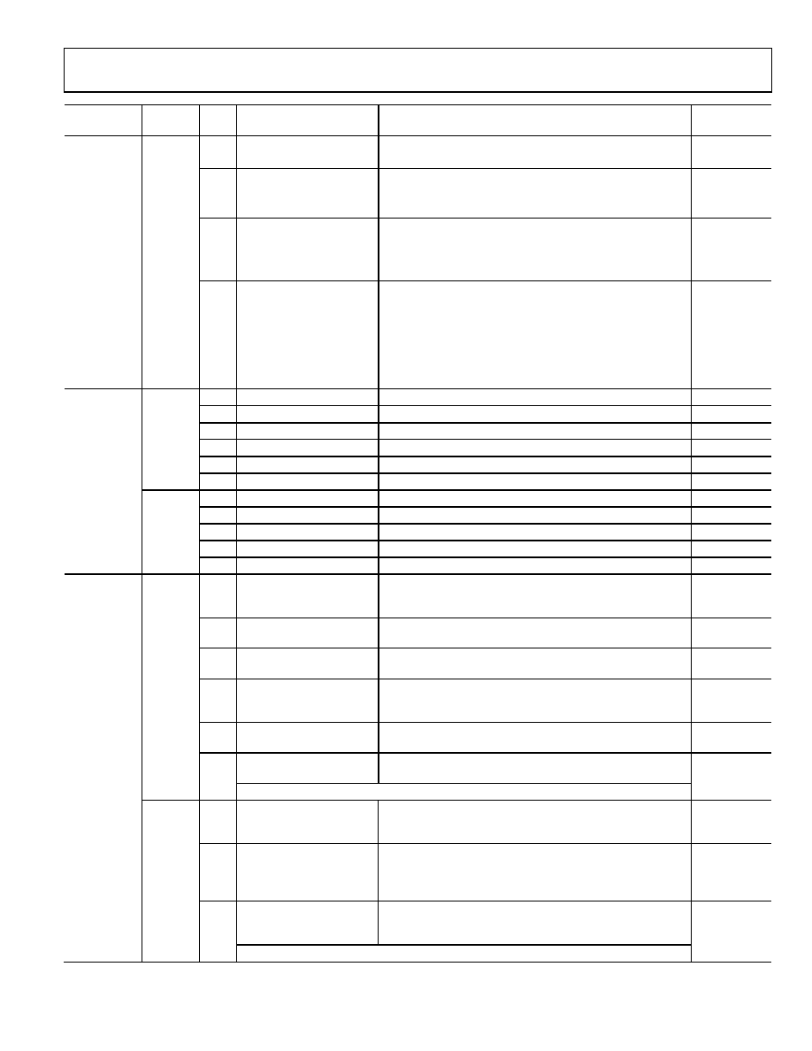
Register
Name
Address
(Hex)
Bits
Name
Description
Default
Data Format
0x03
7
Binary data format
0 = input data is in twos complement format.
0
1 = input data is in binary format.
6
Q data first
Indicates I/Q data pairing on data input.
0
0 = I data sent to data receiver first.
1 = Q data sent to data receiver first.
5
MSB swap
Swaps the bit order of the data input port.
0
0 = order of the data bits corresponds to the pin descriptions.
1 = bit designations are swapped; most significant bits
become the least significant bits.
[1:0]
Data Bus Width[1:0]
Data receiver interface mode. See the LVDS Input Data Ports
section for information about the operation of the different
interface modes.
00
00 = byte mode; 8-bit interface bus width.
01 = byte mode; 8-bit interface bus width.
10 = nibble mode; 4-bit interface bus width.
11 = invalid.
Interrupt
Enable
0x04
7
Enable PLL lock lost
1 = enable interrupt for PLL lock lost.
0
6
Enable PLL locked
1 = enable interrupt for PLL locked.
0
5
Enable sync signal lost
1 = enable interrupt for sync signal lost.
0
4
Enable sync signal locked
1 = enable interrupt for sync signal locked.
0
1
Enable FIFO Warning 1
1 = enable interrupt for FIFO Warning 1.
0
Enable FIFO Warning 2
1 = enable interrupt for FIFO Warning 2.
0
0x05
[7:5]
Set to 0
Set these bits to 0.
000
4
Enable AED compare pass
1 = enable interrupt for AED comparison pass.
0
3
Enable AED compare fail
1 = enable interrupt for AED comparison fail.
0
2
Enable SED compare fail
1 = enable interrupt for SED comparison fail.
0
[1:0]
Set to 0
Set these bits to 0.
00
Event Flag
0x06
7
PLL lock lost
1 = indicates that the PLL, which had been previously
locked, has unlocked from the reference signal. This is a
latched signal.
N/A
6
PLL locked
1 = indicates that the PLL has locked to the reference
clock input.
N/A
5
Sync signal lost
1 = indicates that the sync logic, which had been previously
locked, has lost alignment. This is a latched signal.
N/A
4
Sync signal locked
1 = indicates that the sync logic has achieved sync
alignment. This is indicated when no phase changes
were requested for at least a few full averaging cycles.
N/A
1
FIFO Warning 1
1 = indicates that the difference between the FIFO read
and write pointers is 1.
N/A
0
FIFO Warning 2
1 = indicates that the difference between the FIFO read
and write pointers is 2.
N/A
Note that all event flags are cleared by writing the respective bit high.
0x07
4
AED compare pass
1 = indicates that the SED logic detected a valid input data
pattern compared against the preprogrammed expected
values. This is a latched signal.
N/A
3
AED compare fail
1 = indicates that the SED logic detected an invalid input data
pattern compared against the preprogrammed expected
values. This latched signal is automatically cleared when
eight valid I/Q data pairs are received.
N/A
2
SED compare fail
1 = indicates that the SED logic detected an invalid input
data pattern compared against the preprogrammed
expected values. This is a latched signal.
N/A
Note that all event flags are cleared by writing the respective bit high.
相关PDF资料 |
PDF描述 |
|---|---|
| GTC02R-36-5P | CONN RCPT 4POS BOX MNT W/PINS |
| VE-2TY-MX-F2 | CONVERTER MOD DC/DC 3.3V 49.5W |
| MS27508E24B4PC | CONN RCPT 56POS BOX MNT W/PINS |
| VE-2TY-MW-F2 | CONVERTER MOD DC/DC 3.3V 66W |
| MS27508E24B4PB | CONN RCPT 56POS BOX MNT W/PINS |
相关代理商/技术参数 |
参数描述 |
|---|---|
| AD9146BCPZRL | 功能描述:IC DAC 16BIT SRL DUAL 48LFCSP RoHS:是 类别:集成电路 (IC) >> 数据采集 - 数模转换器 系列:TxDAC+® 产品培训模块:Lead (SnPb) Finish for COTS Obsolescence Mitigation Program 标准包装:1,000 系列:- 设置时间:1µs 位数:8 数据接口:串行 转换器数目:8 电压电源:双 ± 功率耗散(最大):941mW 工作温度:0°C ~ 70°C 安装类型:表面贴装 封装/外壳:24-SOIC(0.295",7.50mm 宽) 供应商设备封装:24-SOIC W 包装:带卷 (TR) 输出数目和类型:8 电压,单极 采样率(每秒):* |
| AD9146-EBZ | 制造商:Analog Devices 功能描述:16 BIT DUAL SIGNAL PROC DAC EB - Boxed Product (Development Kits) |
| AD9146-M5375-EBZ | 功能描述:BOARD EVAL FOR AD9146 DAC RoHS:是 类别:编程器,开发系统 >> 评估板 - 数模转换器 (DAC) 系列:TxDAC+® 产品培训模块:Lead (SnPb) Finish for COTS Obsolescence Mitigation Program 标准包装:1 系列:- DAC 的数量:4 位数:12 采样率(每秒):- 数据接口:串行,SPI? 设置时间:3µs DAC 型:电流/电压 工作温度:-40°C ~ 85°C 已供物品:板 已用 IC / 零件:MAX5581 |
| AD9148 | 制造商:AD 制造商全称:Analog Devices 功能描述:Quad 16-Bit,1 GSPS, TxDAC+ Digital-to-Analog Converter |
| AD9148ARUZ | 制造商:Analog Devices 功能描述:- Rail/Tube |
发布紧急采购,3分钟左右您将得到回复。