- 您现在的位置:买卖IC网 > PDF目录2063 > ADAU1461WBCPZ-R7 (Analog Devices Inc)IC SIGMADSP 24BIT 96KHZ PLL 32 PDF资料下载
参数资料
| 型号: | ADAU1461WBCPZ-R7 |
| 厂商: | Analog Devices Inc |
| 文件页数: | 28/88页 |
| 文件大小: | 0K |
| 描述: | IC SIGMADSP 24BIT 96KHZ PLL 32 |
| 标准包装: | 1,500 |
| 系列: | SigmaDSP® |
| 类型: | 音频处理器 |
| 应用: | 车载音频 |
| 安装类型: | 表面贴装 |
| 封装/外壳: | 32-VFQFN 裸露焊盘,CSP |
| 供应商设备封装: | 32-LFCSP-VQ |
| 包装: | 带卷 (TR) |
第1页第2页第3页第4页第5页第6页第7页第8页第9页第10页第11页第12页第13页第14页第15页第16页第17页第18页第19页第20页第21页第22页第23页第24页第25页第26页第27页当前第28页第29页第30页第31页第32页第33页第34页第35页第36页第37页第38页第39页第40页第41页第42页第43页第44页第45页第46页第47页第48页第49页第50页第51页第52页第53页第54页第55页第56页第57页第58页第59页第60页第61页第62页第63页第64页第65页第66页第67页第68页第69页第70页第71页第72页第73页第74页第75页第76页第77页第78页第79页第80页第81页第82页第83页第84页第85页第86页第87页第88页
ADAU1461
Rev. 0 | Page 34 of 88
HEADPHONE OUTPUT
The LHP and RHP pins can be driven by either a line output
driver or a headphone driver by setting the HPMODE bit in
Register R30 (playback headphone right volume control register,
Address 0x4024). The headphone outputs can drive a load of at
least 16 Ω.
Separate volume controls for the left and right channels range
from 57 dB to +6 dB. Slew can be applied to all the playback
volume controls using the ASLEW[1:0] bits in Register R34
(playback pop/click suppression register, Address 0x4028).
Capless Headphone Configuration
The headphone outputs can be configured in a capless output
configuration with the MONOOUT pin used as a dc virtual
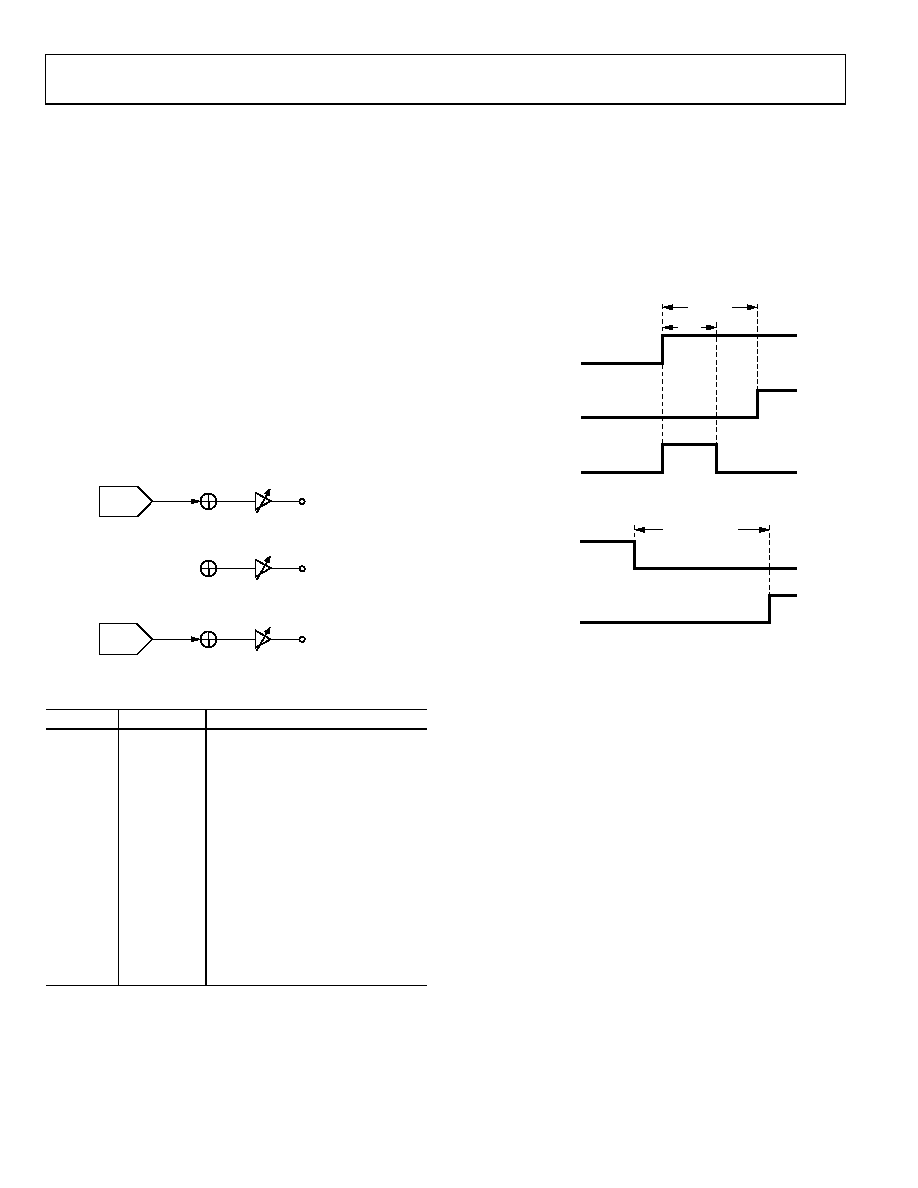
ground reference. Figure 45 depicts a typical playback path in
a capless headphone configuration. Table 18 lists the register
settings for this configuration. As shown in this table, the
MONOOUT pin outputs common mode (AVDD/2), which
is used as the virtual headphone reference.
LHP
MONOOUT
MIXER 3
LEFT
DAC
MX3LM
LHPVOL[5:0]
MX3EN
RHP
MIXER 4
RHPVOL[5:0]
RIGHT
DAC
MX4RM
MX4EN
MIXER 7
MX7[1:0]
MONOM
MOMODE
MX7EN
08
91
4-
0
6
2
Figure 45. Capless Headphone Configuration Diagram
Table 18. Capless Headphone Register Settings
Register
Bit Name
Setting
R36
DACEN[1:0]
11 = both DACs on
R22
MX3EN
1 = enable Mixer 3
MX3LM
1 = unmute left DAC input
R24
MX4EN
1 = enable Mixer 4
MX4RM
1 = unmute right DAC input
R28
MX7EN
1 = enable Mixer 7
MX7[1:0]
00 = common-mode output
R33
MONOM
1 = unmute mono output
MOMODE
1 = headphone output
R29
LHPVOL[5:0]
Desired volume for LHP output
LHPM
1 = unmute left headphone output
R30
HPMODE
1 = headphone output
RHPVOL[5:0]
Desired volume for RHP output
RHPM
1 = unmute right headphone output
Headphone Output Power-Up/Power-Down Sequencing
To prevent pops when turning on the headphone outputs, the
user must wait at least 4 ms to unmute these outputs after
enabling the headphone output with the HPMODE bit. This is
because of an internal capacitor that must charge before these
headphone power-up/power-down sequencing.
For capless headphones, configure the MONOOUT pin before
unmuting the headphone outputs.
USER
DEFINED
4ms
HPMODE
1 = HEADPHONE
INTERNAL
PRECHARGE
RHPM AND LHPM
1 = UNMUTE
08
91
4-
04
6
Figure 46. Headphone Output Power-Up Timing
USER DEFINED
08
91
4-
04
7
HPMODE
0 = LINE OUTPUT
RHPM AND LHPM
0 = MUTE
Figure 47. Headphone Output Power-Down Timing
Ground-Centered Headphone Configuration
The headphone outputs can also be configured as ground-
centered outputs by placing coupling capacitors on the LHP
and RHP pins. Ground-centered headphones should use the
AGND pin as the ground reference.
When the headphone outputs are configured in this manner,
the capacitors create a high-pass filter on the outputs. The
corner frequency of this filter, at which point its attenuation
is 3 dB, is calculated by the following formula:
f3dB = 1/(2π × R × C)
where:
C is the capacitor value.
R is the impedance of the headphones.
For a typical headphone impedance of 16 Ω and a 47 μF
capacitor, the corner frequency is 211 Hz.
相关PDF资料 |
PDF描述 |
|---|---|
| ADAU1513ACPZ-RL7 | IC AMP AUDIO PWR 23W 48LFCSP |
| ADAU1590ACPZ-RL7 | IC AMP AUDIO PWR 48LFCSP |
| ADAU1592ACPZ | IC AMP AUDIO PWR 24W 48LFCSP |
| ADAU1701JSTZ-RL | IC AUDIO PROC 2ADC/4DAC 48-LQFP |
| ADAU1702JSTZ-RL | IC AUDIO PROC 2ADC/4DAC 48-LQFP |
相关代理商/技术参数 |
参数描述 |
|---|---|
| ADAU1461WBCPZ-RL | 功能描述:IC SIGMADSP 24BIT 96KHZ PLL 32 RoHS:是 类别:集成电路 (IC) >> 线性 - 音频处理 系列:SigmaDSP® 其它有关文件:STA321 View All Specifications 标准包装:1 系列:Sound Terminal™ 类型:音频处理器 应用:数字音频 安装类型:表面贴装 封装/外壳:64-LQFP 裸露焊盘 供应商设备封装:64-LQFP EP(10x10) 包装:Digi-Reel® 其它名称:497-11050-6 |
| ADAU1462WBCPZ150 | 功能描述:32BIT SIGMADSP AUDIO 16K/48K 制造商:analog devices inc. 系列:* 包装:管件 零件状态:在售 安装类型:表面贴装 封装/外壳:72-VFQFN 裸露焊盘,CSP 供应商器件封装:72-LFCSP(10x10) 标准包装:1 |
| ADAU1462WBCPZ150RL | 功能描述:32BIT SIGMADSP AUDIO 16K/48K 制造商:analog devices inc. 系列:* 包装:带卷(TR) 零件状态:在售 安装类型:表面贴装 封装/外壳:72-VFQFN 裸露焊盘,CSP 供应商器件封装:72-LFCSP(10x10) 标准包装:2,000 |
| ADAU1462WBCPZ300 | 功能描述:32BIT SIGMADSP AUDIO 16K/48K 制造商:analog devices inc. 系列:* 包装:管件 零件状态:在售 安装类型:表面贴装 封装/外壳:72-VFQFN 裸露焊盘,CSP 供应商器件封装:72-LFCSP(10x10) 标准包装:1 |
| ADAU1462WBCPZ300RL | 功能描述:32BIT SIGMADSP AUDIO 16K/48K 制造商:analog devices inc. 系列:* 包装:带卷(TR) 零件状态:在售 安装类型:表面贴装 封装/外壳:72-VFQFN 裸露焊盘,CSP 供应商器件封装:72-LFCSP(10x10) 标准包装:2,000 |
发布紧急采购,3分钟左右您将得到回复。