- 您现在的位置:买卖IC网 > PDF目录16615 > DC859A (Linear Technology)EVAL BOARD FOR LTC4267 PDF资料下载
参数资料
| 型号: | DC859A |
| 厂商: | Linear Technology |
| 文件页数: | 3/32页 |
| 文件大小: | 0K |
| 描述: | EVAL BOARD FOR LTC4267 |
| 设计资源: | DC859A Design File DC859A Schematic |
| 标准包装: | 1 |
| 主要目的: | 电源管理,以太网供电(POE) |
| 嵌入式: | 否 |
| 已用 IC / 零件: | LTC4267 |
| 已供物品: | 板 |
第1页第2页当前第3页第4页第5页第6页第7页第8页第9页第10页第11页第12页第13页第14页第15页第16页第17页第18页第19页第20页第21页第22页第23页第24页第25页第26页第27页第28页第29页第30页第31页第32页
LTC4267
11
4267fc
Series Diodes
The IEEE 802.3af-dened operating modes for a PD refer-
ence the input voltage at the RJ45 connector on the PD.
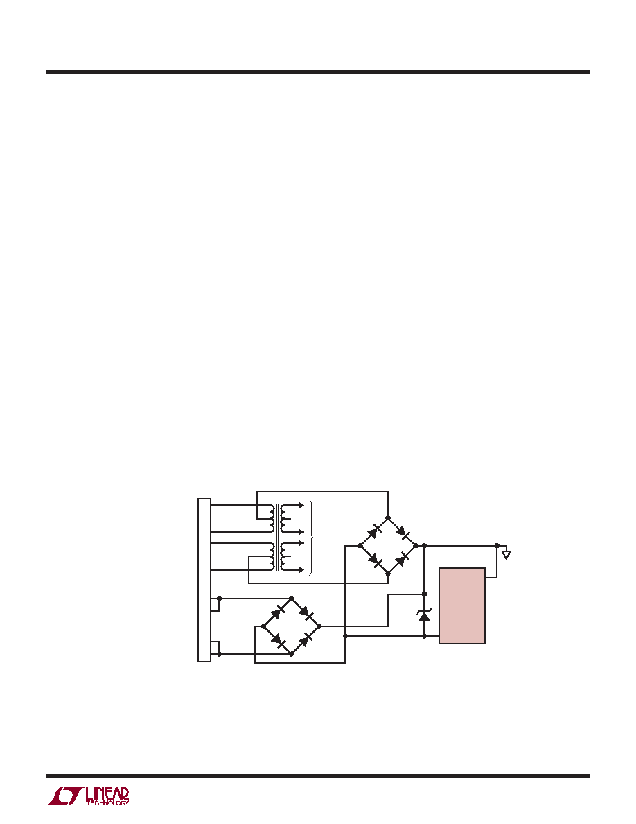
The PD must be able to accept power of either polarity
at each of its inputs, so it is common to install diode
bridges (Figure 2). The LTC4267 takes this into account
by compensating for these diode drops in the threshold
points for each range of operation. A similar adjustment
is made for the UVLO voltages.
Detection
During detection, the PSE will apply a voltage in the
range of – 2.8V to –10V on the cable and look for a 25kΩ
signature resistor. This identies the device at the end of
the cable as a PD. With the terminal voltage in this range,
the LTC4267 connects an internal 25kΩ resistor between
the VPORTP and VPORTN pins. This precision, temperature
compensated resistor presents the proper signature to
alert the PSE that a PD is present and desires power to be
applied. The internal low-leakage UVLO switch prevents
the switching regulator circuitry from affecting the detec-
tion signature.
The LTC4267 is designed to compensate for the voltage
and resistance effects of the IEEE required diode bridge.
The signature range extends below the IEEE range to ac-
commodate the voltage drop of the two diodes. The IEEE
specication requires the PSE to use a ΔV/ΔI measurement
technique to keep the DC offset of these diodes from af-
fecting the signature resistance measurement. However,
the diode resistance appears in series with the signature
resistor and must be included in the overall signature
resistance of the PD. The LTC4267 compensates for the
two series diodes in the signature path by offsetting the
resistance so that a PD built using the LTC4267 will meet
the IEEE specication.
In some applications it is necessary to control whether or
not the PD is detected. In this case, the 25kΩ signature
resistor can be enabled and disabled with the use of the
SIGDISA pin (Figure 3). Disabling the signature via the
SIGDISA pin will change the signature resistor to 9kΩ
(typical) which is an invalid signature per the IEEE 802.3af
specication. This invalid signature is present for PD input
voltages from –2.8V to –10V. If the input rises above –10V,
the signature resistor reverts to 25kΩ to minimize power
dissipation in the LTC4267. To disable the signature, tie
SIGDISA to VPORTP. Alternately, the SIGDISA pin can be
driven high with respect to VPORTN. When SIGDISA is high,
all functions of the PD interface are disabled.
APPLICATIO S I FOR ATIO
WU
UU
RX–
6
RX+
3
TX–
2
TX+
RJ45
T1
POWERED DEVICE (PD)
INTERFACE
AS DEFINED
BY IEEE 802.3af
4267 F02
1
7
8
5
4
SPARE–
SPARE+
TO PHY
BR2
BR1
VPORTP
8
4
D3
LTC4267
VPORTN
Figure 2. LTC4267 PD Front End Using
Diode Bridges on Main and Spare Inputs
相关PDF资料 |
PDF描述 |
|---|---|
| P1812R-104K | INDUCTOR POWER 100UH SMD |
| EBA28DTKN-S288 | CONN EDGECARD 56POS .125 EXTEND |
| A3AAB-2606M | IDC CABLE- ASC26B/AE26M/ASC26B |
| EB41-S0K1060X | CONN EDGEBOARD DUAL 20POS 3A |
| H3AKH-3018G | IDC CABLE - HSC30H/AE30G/HPK30H |
相关代理商/技术参数 |
参数描述 |
|---|---|
| DC-85FMMT | 制造商:Polycase 功能描述:Enclosure;Flanged;PanelMount;ABS,UL94-5VA;Black;8.25x5x4.33 In;DC Series |
| DC-85FMMT01 | 制造商:Polycase 功能描述:Enclosure;Flanged;PanelMount;ABS,UL94-5VA;Gray;8.25x5x4.33 In;DC Series |
| DC-85PMMT | 制造商:Polycase 功能描述:Enclosure;Box-Lid;Desktop;ABS,UL94-5VA;Black;8.25x5x4.33 In;DC Series |
| DC-85PMMT01 | 制造商:Polycase 功能描述:Enclosure;Box-Lid;Desktop;ABS,UL94-5VA;Gray;8.25x5x4.33 In;DC Series |
| DC872A | 制造商:Linear Technology 功能描述:DEMO BOARD FOR LTC4213CDD 制造商:Linear Technology 功能描述:EVAL BOARD, LTC4213CDD OVERVOLTAGE PROT |
发布紧急采购,3分钟左右您将得到回复。