- 您现在的位置:买卖IC网 > PDF目录16560 > EVAL-ADF4193EBZ2 (Analog Devices Inc)BOARD EVALUATION EB2 FOR ADF4193 PDF资料下载
参数资料
| 型号: | EVAL-ADF4193EBZ2 |
| 厂商: | Analog Devices Inc |
| 文件页数: | 14/32页 |
| 文件大小: | 0K |
| 描述: | BOARD EVALUATION EB2 FOR ADF4193 |
| 标准包装: | 1 |
| 主要目的: | 计时,频率合成器 |
| 嵌入式: | 否 |
| 已用 IC / 零件: | ADF4193 |
| 主要属性: | 400 MHz ~ 3.5 GHz,数字式可编程输出相位 |
| 次要属性: | 板不包括环路滤波器和 VCO |
| 已供物品: | 板,缆线,CD |
| 相关产品: | ADF4193BCPZ-ND - IC PLL FREQ SYNTHESIZER 32LFCSP ADF4193BCPZ-RL7-ND - IC PLL FREQ SYNTHESIZER 32LFCSP ADF4193BCPZ-RL-ND - IC PLL FREQ SYNTHESIZER 32LFCSP |
第1页第2页第3页第4页第5页第6页第7页第8页第9页第10页第11页第12页第13页当前第14页第15页第16页第17页第18页第19页第20页第21页第22页第23页第24页第25页第26页第27页第28页第29页第30页第31页第32页
Data Sheet
ADF4193
Rev. F | Page 21 of 32
MUX REGISTER (R6)
05328-
029
DB15
M13
DB14
M12
DB13
M11
DB12
M10
DB11
0
DB10
0
DB9
0
DB8
0
DB7
0
DB6
M4
DB5
M3
DB4
M2
DB3
M1
DB2
C3 (1)
DB1
C2 (1)
DB0
C1 (0)
RESERVED
MUXOUT
CONTROL
BITS
SIGMA-DELTA
AND
LOCK DETECT MODES
0
1
M10
0
1
0
M11
0
ALL OTHER STATES
M12
0
1
M13
INIT STATE, DITHER OFF,
3ns LOCK DETECT THRESHOLD
DITHER ON
10ns LOCK DETECT THRESHOLD
RESERVED
SIGMA-DELTA MODES
0
1
M4
0
1
0
1
M3
0
1
0
1
0
1
0
1
M2
0
1
0
1
0
1
0
1
0
1
0
1
0
1
0
1
M1
3-STATE
DIGITAL LOCK DETECT
N DIVIDER OUTPUT
LOGIC HIGH
R COUNTER
RESERVED
SERIAL DATA OUT
LOGIC LOW
R DIVIDER/2 OUTPUT
N DIVIDER/2 OUTPUT
RESERVED
ICP TIMEOUT SIGNAL
SW1/2 TIMEOUT SIGNAL
SW3 TIMEOUT SIGNAL
RESERVED
MUXOUT
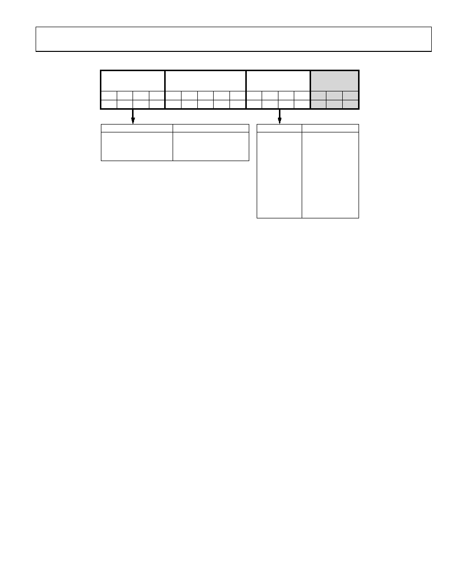
Figure 35. MUX Register (R6)
With C3, C2, and C1 set to 1, 1, 0, respectively, the MUX
register is programmed.
Σ-Δ and Lock Detect Modes
Bit DB15 to Bit DB12 are used to reconfigure certain PLL
operating modes. In the initialization sequence after power is
applied to the chip, the four bits must first be programmed to
all zeros. This initializes the PLL to a known state with dither
off in the Σ-Δ modulator and a 3 ns PFD error threshold in the
lock detect circuit.
To turn on dither in the Σ-Δ modulator, an additional write
should be made to Register R6 to program bits [DB15:DB12] =
[0011]. However, for lowest noise operation, it is best to leave
dither off.
To change the lock detect threshold from 3 ns to 10 ns, a
separate write to R6 should be performed to program bits
[DB15:DB12] = [1001]. This should be done for reliable lock
detect operation when the RF frequency is <2 GHz.
A write to R6 that programs bits [DB15:DB12] = [0000] returns
operation to the default state with both dither off and a 3 ns
lock detect threshold.
Reserved Bits
The reserved bits must all be set to 0 for normal operation.
MUXOUT Modes
These bits control the on-chip multiplexer. See Figure 35 for the
truth table. This pin is useful for diagnosis because it allows the
user to look at various internal points of the chip, such as the
R divider and INT divider outputs.
In addition, it is possible to monitor the programmed timeout
counter intervals on MUXOUT. For example, if the ICP timeout
counter was programmed to 65 (with a 26 MHz PFD), then
following the next write to R0, a pulse width of 10 s would be
observed on the MUXOUT pin.
Digital lock detect is available via the MUXOUT pin.
相关PDF资料 |
PDF描述 |
|---|---|
| RMC06DRTH-S734 | CONN EDGECARD 12POS DIP .100 SLD |
| HBM18DSUN | CONN EDGECARD 36POS .156 DIP SLD |
| RSC06DREI-S734 | CONN EDGECARD 12POS .100 EYELET |
| EBA24DRMI | CONN EDGECARD 48POS .125 SQ WW |
| MAX8663ETL+T | IC PMIC LI+ SNGL CELL 40TQFN |
相关代理商/技术参数 |
参数描述 |
|---|---|
| EVAL-ADF4206-7EB1 | 制造商:Analog Devices 功能描述:EVALUATION BOARD FOR DUAL RF PLL FREQUENCY SYNTHESIZERS 制造商:Analog Devices 功能描述:DUAL RF PLL FREQ SYNTHESIZERS - Bulk |
| EVAL-ADF4208EB1 | 制造商:Analog Devices 功能描述:Evaluation Board For Dual RF PLL Frequency Synthesizers 制造商:Analog Devices 功能描述:DUAL RF PLL FREQ SYNTHESIZERS - Bulk |
| EVAL-ADF4212EB1 | 制造商:Analog Devices 功能描述:EVALUATION BOARD I.C. - Bulk |
| EVAL-ADF4213EB1 | 制造商:Analog Devices 功能描述:EVALUATION BOARD I.C. - Bulk |
| EVAL-ADF4213EB2 | 制造商:Analog Devices 功能描述:EVALUATION BOARD I.C. - Bulk |
发布紧急采购,3分钟左右您将得到回复。