- 您现在的位置:买卖IC网 > PDF目录67685 > ICS5342 PALETTE-DAC DSPL CTLR, PQCC68 PDF资料下载
参数资料
| 型号: | ICS5342 |
| 元件分类: | 显示控制器 |
| 英文描述: | PALETTE-DAC DSPL CTLR, PQCC68 |
| 封装: | PLASTIC, LCC-68 |
| 文件页数: | 8/36页 |
| 文件大小: | 1017K |
| 代理商: | ICS5342 |
第1页第2页第3页第4页第5页第6页第7页当前第8页第9页第10页第11页第12页第13页第14页第15页第16页第17页第18页第19页第20页第21页第22页第23页第24页第25页第26页第27页第28页第29页第30页第31页第32页第33页第34页第35页第36页
ICS5342
GENDAC
16
lined to the DAC. The pipeline delay from input to DAC out-
put is three PCLK cycles. Each color is 5-bit wide as shown
below. This mode is selected by setting bits CR7-CR4 to
0011.
3LSB = set to zero
Mode 6: (16-bit pixel interface, 16-bit per color bypass XGA
mode) In this mode input P0-P15 are the color data and are in-
put directly to the DAC bypassing the color palette. The data
is latched by the rising edge of PCLK and is pipelined to the
DAC. The pipeline delay, from input to DAC output, is three
PCLK cycles. In this mode Blue and Red colors are 5 bits
wide, and Green is 6 bits wide. This mode is selected by set-
ting bits CR7-CR4 to 0101.
2LSB = set to zero (GREEN)
3LSB = set to zero (BLUE, RED)
Mode 7: (16-bit pixel interface, 24-bit per color bypass
TRUE color mode) In this mode inputs P0-P15 are the color
data and are input directly to the DAC bypassing the color pal-
ette. Two words are latched on two successive rising edge of
PCLK to form the 24-bit DAC input. The first word and the
lower byte of the second word form the 24-bit pixel input to
the DAC. The higher byte of the second word is ignored. The
low and high word synchronization is internally done by the
rising edge of BLANK*. The pipeline delay from latching of
the first word to DAC output is 4 cycles and each pixel is two
pixel clocks wide. In this mode, each of the colors are 8-bits
wide and the DAC is 8-bit wide DAC. The first byte is Blue
followed by Green and Red. This mode is selected by setting
bits CR7-CR4 to 0111.
Mode 8: (16-bit pixel interface packed 24-bit per color bypass
TRUE color mode) In this mode inputs P0-P15 are the color
data and are input directly to the DAC bypassing the color pal-
ette. Three words are latched on three successive rising edges
of PCLK to form two successive 24-bit DAC inputs. The 16-
bit first word and the lower byte of the second word from the
first 24-bit pixel input and the second byte of the second word
with the 16 bits of the third word from the second 24-bit pixel
input. This cycle repeats every three cycles. The three-word
synchronization is internally done by the rising edge of
BLANK*. The pipeline delay from latching of first word to
DAC output is 3 1/2 cycles and each of the colors are 8-bits
wide and DAC is 8-bit wide DAC. The first byte is Blue fol-
lowed by Green and Red. This mode is selected by setting bits
CR7-CR4 to 1001.
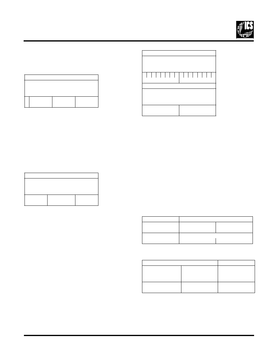
15-Bit Color Word - Mode 5
PIXEL WORD
PPPPPPPPPPPPPPPP
1111119876543210
543210
X 7 65547654376543
X
RED
GREEN
BLUE
16-Bit Color Word - Mode 6
PIXEL WORD
PPPPPPPPPPPPPPPP
1111119876543210
543210
7654376543276543
RED
GREEN
BLUE
24-Bit Direct Color Word - Mode 7
FIRST WORD
PPPPPPPPPPPPPPPP
1111119876543210
543210
7654321076543210
GREEN
BLUE
SECOND WORD
PPPPPPPPPPPPPPPP
1111119876543210
543210
XXXXXXXX7 6 5 43210
IGNORED
RED
Packed 24-bit Word - Mode 8
1st DAC Cycle
SECOND WORD
FIRST WORD
PPPPPPPPPPPPPPPPPPPPPPPP
765432101111119876543210
765432105432109876543210
RED
GREEN
BLUE
2nd DAC Cycle
THIRD WORD
SECOND WORD
PPPPPPPP PPPPPPPPPPPPPPPP
111111987 6 5 4321011111198
543210
5 43210
765432107 6 5 4321076543210
RED
GREEN
BLUE
相关PDF资料 |
PDF描述 |
|---|---|
| ICS552ARI-01LFT | 200 MHz, OTHER CLOCK GENERATOR, PDSO20 |
| ICS552R-01ILF | 200 MHz, OTHER CLOCK GENERATOR, PDSO20 |
| ICS557G-05ATR | 200 MHz, PROC SPECIFIC CLOCK GENERATOR, PDSO20 |
| ICS557G-08LF | 557 SERIES, LOW SKEW CLOCK DRIVER, 1 TRUE OUTPUT(S), 0 INVERTED OUTPUT(S), PDSO16 |
| ICS557G-08LFT | 557 SERIES, LOW SKEW CLOCK DRIVER, 1 TRUE OUTPUT(S), 0 INVERTED OUTPUT(S), PDSO16 |
相关代理商/技术参数 |
参数描述 |
|---|---|
| ICS5342-1 | 制造商:ICS 制造商全称:ICS 功能描述:Analog IC |
| ICS5342-2 | 制造商:ICS 制造商全称:ICS 功能描述:Analog IC |
| ICS5342-3 | 制造商:ICS 制造商全称:ICS 功能描述:Analog IC |
| ICS5342ADD | 制造商:ICS 制造商全称:ICS 功能描述:Addendum to ICS5342 Data Sheet |
| ICS5342V | 制造商:未知厂家 制造商全称:未知厂家 功能描述:Peripheral IC |
发布紧急采购,3分钟左右您将得到回复。