参数资料
| 型号: | ISL6277IRZ |
| 厂商: | Intersil |
| 文件页数: | 28/37页 |
| 文件大小: | 0K |
| 描述: | IC PWM REG MULTIPH AMD 48-QFN |
| 标准包装: | 50 |
| 应用: | 控制器,AMD Fusion? SVI 2.0 CPU GPU |
| 输入电压: | 4.5 V ~ 25 V |
| 输出数: | 2 |
| 输出电压: | 0.006 V ~ 1.55 V |
| 工作温度: | -40°C ~ 85°C |
| 安装类型: | 表面贴装 |
| 封装/外壳: | 48-VFQFN 裸露焊盘 |
| 供应商设备封装: | 48-QFN(6x6) |
| 包装: | 管件 |
第1页第2页第3页第4页第5页第6页第7页第8页第9页第10页第11页第12页第13页第14页第15页第16页第17页第18页第19页第20页第21页第22页第23页第24页第25页第26页第27页当前第28页第29页第30页第31页第32页第33页第34页第35页第36页第37页
�� �
�
�ISL6277�
�?� L� =� -------------�
�Key� Component� Selection�
�Inductor� DCR� Current-Sensing� Network�
�DCR�
�L�
�(EQ.� 20)�
�?� sns� =� --------------------------------------------------------�
�R� ntcnet� ?� ---------------�
�------------------------------------------� ?� C� n�
�R� ntcnet� +� ---------------�
�PHASE1� PHASE2� PHASE3�
�R� SUM�
�R� SUM�
�R� SUM�
�I� SUM+�
�1�
�R� sum�
�N�
�R� sum�
�N�
�where� N� is� the� number� of� phases.�
�(EQ.� 21)�
�L�
�DCR�
�L�
�DCR�
�L�
�DCR�
�R� NTCS�
�R� NTC�
�R� O�
�R� P�
�+�
�CN� VCN�
�-�
�RI�
�I� SUM-�
�Transfer� function� A� cs� (s)� always� has� unity� gain� at� DC.� The� inductor�
�DCR� value� increases� as� the� winding� temperature� increases,�
�giving� higher� reading� of� the� inductor� DC� current.� The� NTC� R� ntc�
�value� decrease� as� its� temperature� decreases.� Proper� selection� of�
�R� sum� ,� R� ntcs� ,� R� p� and� R� ntc� parameters� ensures� that� V� Cn�
�represents� the� inductor� total� DC� current� over� the� temperature�
�R� O�
�R� O�
�I� O�
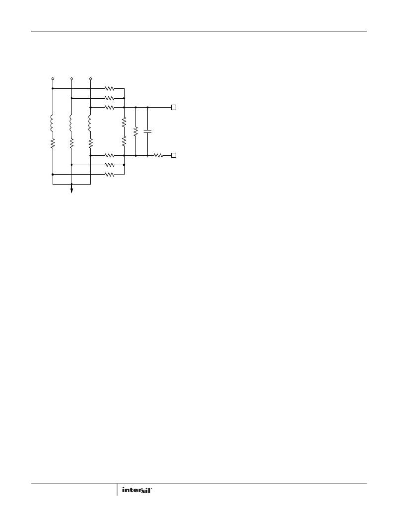
�FIGURE� 22.� DCR� CURRENT-SENSING� NETWORK�
�Figure� 22� shows� the� inductor� DCR� current-sensing� network� for� a�
�3-phase� solution.� An� inductor� current� flows� through� the� DCR� and�
�creates� a� voltage� drop.� Each� inductor� has� two� resistors� in� R� sum�
�and� R� o� connected� to� the� pads� to� accurately� sense� the� inductor�
�current� by� sensing� the� DCR� voltage� drop.� The� R� sum� and� R� o�
�resistors� are� connected� in� a� summing� network� as� shown,� and� feed�
�the� total� current� information� to� the� NTC� network� (consisting� of�
�R� ntcs� ,� R� ntc� and� R� p� )� and� capacitor� C� n� .� R� ntc� is� a� negative�
�temperature� coefficient� (NTC)� thermistor,� used� to� temperature�
�compensate� the� inductor� DCR� change.�
�The� inductor� output� side� pads� are� electrically� shorted� in� the�
�schematic� but� have� some� parasitic� impedance� in� actual� board�
�layout,� which� is� why� one� cannot� simply� short� them� together� for� the�
�current-sensing� summing� network.� It� is� recommended� to� use�
�1� ?� ~10� ?� ?� R� o� to� create� quality� signals.� Since� R� o� value� is� much� smaller�
�than� the� rest� of� the� current� sensing� circuit,� the� following� analysis�
�range� of� interest.�
�There� are� many� sets� of� parameters� that� can� properly�
�temperature-compensate� the� DCR� change.� Since� the� NTC�
�network� and� the� R� sum� resistors� form� a� voltage� divider,� V� cn� is�
�always� a� fraction� of� the� inductor� DCR� voltage.� It� is� recommended�
�to� have� a� higher� ratio� of� V� cn� to� the� inductor� DCR� voltage� so� the�
�droop� circuit� has� a� higher� signal� level� to� work� with.�
�A� typical� set� of� parameters� that� provide� good� temperature�
�compensation� are:� R� sum� =� 3.65k� ?� ,� R� p� =� 11k� ?� ,� R� ntcs� =� 2.61k� ?�
�and� R� ntc� =� 10k� ?� (ERT-J1VR103J).� The� NTC� network� parameters�
�may� need� to� be� fine� tuned� on� actual� boards.� One� can� apply� full�
�load� DC� current� and� record� the� output� voltage� reading�
�immediately;� then� record� the� output� voltage� reading� again� when�
�the� board� has� reached� the� thermal� steady� state.� A� good� NTC�
�network� can� limit� the� output� voltage� drift� to� within� 2mV.� It� is�
�recommended� to� follow� the� Intersil� evaluation� board� layout� and�
�current� sensing� network� parameters� to� minimize� engineering�
�time.�
�V� Cn� (s)� also� needs� to� represent� real-time� I� o� (s)� for� the� controller� to�
�achieve� good� transient� response.� Transfer� function� A� cs� (s)� has� a�
�pole� w� sns� and� a� zero� w� L� .� One� needs� to� match� w� L� and� w� sns� so�
�A� cs� (s)� is� unity� gain� at� all� frequencies.� By� forcing� w� L� equal� to� w� sns�
�and� solving� for� the� solution,� Equation� 22� gives� Cn� value.�
�C� n� =� ---------------------------------------------------------------�
�R� ntcnet� ?� ---------------�
�------------------------------------------� ?� DCR�
�R� ntcnet� +� ---------------�
�ignores� it.�
�The� summed� inductor� current� information� is� presented� to� the�
�capacitor� C� n� .� Equations� 17� thru� 21� describe� the� frequency�
�domain� relationship� between� inductor� total� current� I� o� (s)� and� C� n�
�voltage� V� Cn� (s):�
�L�
�R� sum�
�N�
�R� sum�
�N�
�(EQ.� 22)�
�V� Cn� ?� s� ?� =� ?� ------------------------------------------� ?� -------------� ?� ?� I� o� ?� s� ?� ?� A� cs� ?� s� ?�
�?� R� ntcnet� +� ---------------� ?�
�R� ntcnet� =� ----------------------------------------------------�
�1� +� -------�
�A� cs� ?� s� ?� =� -----------------------�
�1� +� -------------�
�?� ?�
�?� R� ntcnet� DCR� ?�
�?� R� sum� N� ?�
�N�
�?� R� ntcs� +� R� ntc� ?� ?� R� p�
�R� ntcs� +� R� ntc� +� R� p�
�s�
�?� L�
�s�
�?� sns�
�28�
�(EQ.� 17)�
�(EQ.� 18)�
�(EQ.� 19)�
�For� example,� given� N� =� 3,� R� sum� =� 3.65k� ?� ,� R� p� =� 11k� ?� ,�
�R� ntcs� =� 2.61k� ?� ,� R� ntc� =� 10k� ?� ,� DCR� =� 0.88m� ?� and� L� =� 0.36μH,�
�Equation� 22� gives� C� n� =� 0.406μF.�
�Assuming� the� compensator� design� is� correct,� Figure� 23� shows� the�
�expected� load� transient� response� waveforms� if� C� n� is� correctly�
�selected.� When� the� load� current� I� core� has� a� square� change,� the�
�output� voltage� V� core� also� has� a� square� response.�
�If� C� n� value� is� too� large� or� too� small,� V� Cn� (s)� does� not� accurately�
�represent� real-time� I� o� (s)� and� worsens� the� transient� response.�
�Figure� 24� shows� the� load� transient� response� when� C� n� is� too�
�small.� V� core� sags� excessively� upon� load� insertion� and� may� create�
�a� system� failure.� Figure� 25� shows� the� transient� response� when�
�FN8270.1�
�March� 8,� 2012�
�相关PDF资料 |
PDF描述 |
|---|---|
| HCC22DRXN | CONN EDGECARD 44POS DIP .100 SLD |
| ISL62773HRZ | IC PWM REG MULTIPH AMD 48-QFN |
| 400MXC390MEFCSN30X45 | CAP ALUM 390UF 400V 20% SNAP-IN |
| X40030V14I-A | IC VOLTAGE MONITOR TRPL 14-TSSOP |
| HCC22DRXH | CONN EDGECARD 44POS DIP .100 SLD |
相关代理商/技术参数 |
参数描述 |
|---|---|
| ISL6277IRZ-T | 功能描述:IC PWM REG MULTIPH AMD 48-QFN RoHS:是 类别:集成电路 (IC) >> PMIC - 稳压器 - 专用型 系列:- 标准包装:43 系列:- 应用:控制器,Intel VR11 输入电压:5 V ~ 12 V 输出数:1 输出电压:0.5 V ~ 1.6 V 工作温度:-40°C ~ 85°C 安装类型:表面贴装 封装/外壳:48-VFQFN 裸露焊盘 供应商设备封装:48-QFN(7x7) 包装:管件 |
| ISL62810AHRUZ-T | 制造商:Intersil Corporation 功能描述:0/2-BIT PWM GPU CONTROLLER FOR NOTEBOOK. 20 LD 3.2 X 1.8 UTQ - Tape and Reel 制造商:Intersil 功能描述:0/2 BIT PWM GPU CONTLR FOR NOTEBOOK |
| ISL62810HRUZ-T | 制造商:Intersil Corporation 功能描述:0/2-BIT PWM GPU CONTROLLER FOR NOTEBOOK. 16LD 2.6 X 1.8 UTQF - Tape and Reel 制造商:Intersil 功能描述:0/2 BIT PWM GPU CONTLR FOR NOTEBOOK |
| ISL62870 | 制造商:INTERSIL 制造商全称:Intersil Corporation 功能描述:PWM DC/DC Voltage Regulator Controller |
| ISL62870HRUZ | 制造商:INTERSIL 制造商全称:Intersil Corporation 功能描述:PWM DC/DC Voltage Regulator Controller |
发布紧急采购,3分钟左右您将得到回复。