参数资料
| 型号: | ISL6277IRZ |
| 厂商: | Intersil |
| 文件页数: | 31/37页 |
| 文件大小: | 0K |
| 描述: | IC PWM REG MULTIPH AMD 48-QFN |
| 标准包装: | 50 |
| 应用: | 控制器,AMD Fusion? SVI 2.0 CPU GPU |
| 输入电压: | 4.5 V ~ 25 V |
| 输出数: | 2 |
| 输出电压: | 0.006 V ~ 1.55 V |
| 工作温度: | -40°C ~ 85°C |
| 安装类型: | 表面贴装 |
| 封装/外壳: | 48-VFQFN 裸露焊盘 |
| 供应商设备封装: | 48-QFN(6x6) |
| 包装: | 管件 |
第1页第2页第3页第4页第5页第6页第7页第8页第9页第10页第11页第12页第13页第14页第15页第16页第17页第18页第19页第20页第21页第22页第23页第24页第25页第26页第27页第28页第29页第30页当前第31页第32页第33页第34页第35页第36页第37页
�� �
�
�ISL6277�
�V� droop� R� droop� R� ntcnet� DCR�
�I� o� R� i� R� sum�
�R� ntcnet� +� ---------------�
�Load� Line� Slope�
�See� Figure� 14� for� load-line� implementation.�
�For� inductor� DCR� sensing,� substitution� of� Equation� 27� into�
�Equation� 2� gives� the� load-line� slope� expression:�
�LL� =� -------------------� =� -------------------� ?� ------------------------------------------� ?� -------------� (EQ.� 34)�
�N�
�N�
�For� resistor� sensing,� substitution� of� Equation� 31� into� Equation� 2�
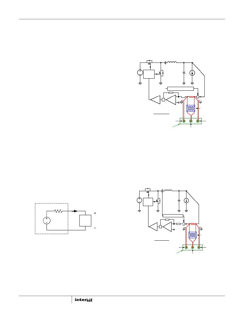
�shows� T2(s)� measurement� set-up.� The� VR� senses� the� inductor�
�current,� multiplies� it� by� a� gain� of� the� load-line� slope,� adds� it� on� top�
�of� the� sensed� output� voltage,� and� then� feeds� it� to� the�
�compensator.� T1� is� measured� after� the� summing� node,� and� T2� is�
�measured� in� the� voltage� loop� before� the� summing� node.� The�
�spreadsheet� gives� both� T1(s)� and� T2(s)� plots.� However,� only� T2(s)�
�can� actually� be� measured� on� an� ISL6277� regulator.�
�L� V� O�
�Q1�
�V� droop� R� sen� ?� R� droop�
�N� ?� R� i�
�gives� the� load� line� slope� expression� :�
�LL� =� -------------------� =� ---------------------------------------�
�I� o�
�(EQ.� 35)�
�V� IN�
�GATE�
�DRIVER�
�Q2�
�C� OUT�
�i� O�
�R� droop� =� ----------------� ?� LL�
�I� o�
�?�
�-�
�Substitution� of� Equation� 28� and� rewriting� Equation� 34,� or�
�substitution� of� Equation� 32� and� rewriting� Equation� 35,� gives� the�
�same� result� as� in� Equation� 36:�
�(EQ.� 36)�
�I� droop�
�LOOP� GAIN� =�
�MOD.�
�COMP�
�CHANNEL� B�
�CHANNEL� A�
�LOAD� LINE� SLOPE�
�20�
�EA�
�+�
�VID�
�+�
�+�
�ISOLATION�
�TRANSFORMER�
�One� can� use� the� full-load� condition� to� calculate� R� droop� .� For�
�example,� given� I� omax� =� 65A,� I� droopmax� =� 45μA� and� LL� =� 2.1m� ?� ,�
�Equation� 36� gives� R� droop� =� 3.03k� ?� .�
�CHANNEL� A�
�NETWORK�
�ANALYZER�
�EXCITATION� OUTPUT�
�CHANNEL� B�
�It� is� recommended� to� start� with� the� R� droop� value� calculated� by�
�Equation� 36� and� fine-tune� it� on� the� actual� board� to� get� accurate�
�load-line� slope.� One� should� record� the� output� voltage� readings� at�
�no� load� and� at� full� load� for� load-line� slope� calculation.� Reading�
�the� output� voltage� at� lighter� load� instead� of� full� load� will� increase�
�the� measurement� error.�
�Compensator�
�Figure� 23� shows� the� desired� load� transient� response� waveforms.�
�Figure� 29� shows� the� equivalent� circuit� of� a� voltage� regulator� (VR)�
�with� the� droop� function.� A� VR� is� equivalent� to� a� voltage� source�
�FIGURE� 30.� LOOP� GAIN� T1(s)� MEASUREMENT� SET-UP�
�T1(s)� is� the� total� loop� gain� of� the� voltage� loop� and� the� droop� loop.�
�It� always� has� a� higher� crossover� frequency� than� T2(s),� therefore�
�has� a� higher� impact� on� system� stability.�
�T2(s)� is� the� voltage� loop� gain� with� closed� droop� loop,� thus� having�
�a� higher� impact� on� output� voltage� response.�
�Design� the� compensator� to� get� stable� T1(s)� and� T2(s)� with� sufficient�
�phase� margin� and� an� output� impedance� equal� to� or� smaller� than�
�the� load-line� slope.�
�(=� VID)� and� output� impedance� Z� out� (s).� If� Z� out� (s)� is� equal� to� the�
�load-line� slope� LL,� i.e.,� a� constant� output� impedance,� then� in� the�
�L�
�V� O�
�entire� frequency� range,� V� o� will� have� a� square� response� when� I� o�
�has� a� square� change.�
�V� IN�
�Q1�
�GATE�
�DRIVER�
�Q2�
�C� O�
�I� O�
�Z� out� (s)� =� LL�
�i�
�o�
�LOAD� LINE� SLOPE�
�o�
�+�
�VID�
�VR�
�LOAD�
�V�
�MOD.�
�COMP�
�-�
�EA�
�+�
�VID�
�+�
�20�
�?�
�ISOLATION�
�TRANSFORMER�
�FIGURE� 29.� VOLTAGE� REGULATOR� EQUIVALENT� CIRCUIT�
�LOOP� GAIN� =�
�CHANNEL� B�
�CHANNEL� A�
�Intersil� provides� a� Microsoft� Excel-based� spreadsheet� to� help�
�design� the� compensator� and� the� current� sensing� network� so� that�
�CHANNEL� A�
�NETWORK�
�ANALYZER�
�EXCITATION� OUTPUT�
�CHANNEL� B�
�VR� achieves� constant� output� impedance� as� a� stable� system.�
�A� VR� with� active� droop� function� is� a� dual-loop� system� consisting� of�
�a� voltage� loop� and� a� droop� loop,� which� is� a� current� loop.� However,�
�neither� loop� alone� is� sufficient� to� describe� the� entire� system.� The�
�spreadsheet� shows� two� loop� gain� transfer� functions,� T1(s)� and�
�T2(s),� that� describe� the� entire� system.� Figure� 30� conceptually�
�shows� T1(s)� measurement� set-up,� and� Figure� 31� conceptually�
�31�
�FIGURE� 31.� LOOP� GAIN� T2(s)� MEASUREMENT� SET-UP�
�Current� Balancing�
�Refer� to� Figures� 15� through� 22� for� information� on� current�
�balancing.� The� ISL6277� achieves� current� balancing� through�
�matching� the� ISEN� pin� voltages.� R� isen� and� C� isen� form� filters� to�
�FN8270.1�
�March� 8,� 2012�
�相关PDF资料 |
PDF描述 |
|---|---|
| HCC22DRXN | CONN EDGECARD 44POS DIP .100 SLD |
| ISL62773HRZ | IC PWM REG MULTIPH AMD 48-QFN |
| 400MXC390MEFCSN30X45 | CAP ALUM 390UF 400V 20% SNAP-IN |
| X40030V14I-A | IC VOLTAGE MONITOR TRPL 14-TSSOP |
| HCC22DRXH | CONN EDGECARD 44POS DIP .100 SLD |
相关代理商/技术参数 |
参数描述 |
|---|---|
| ISL6277IRZ-T | 功能描述:IC PWM REG MULTIPH AMD 48-QFN RoHS:是 类别:集成电路 (IC) >> PMIC - 稳压器 - 专用型 系列:- 标准包装:43 系列:- 应用:控制器,Intel VR11 输入电压:5 V ~ 12 V 输出数:1 输出电压:0.5 V ~ 1.6 V 工作温度:-40°C ~ 85°C 安装类型:表面贴装 封装/外壳:48-VFQFN 裸露焊盘 供应商设备封装:48-QFN(7x7) 包装:管件 |
| ISL62810AHRUZ-T | 制造商:Intersil Corporation 功能描述:0/2-BIT PWM GPU CONTROLLER FOR NOTEBOOK. 20 LD 3.2 X 1.8 UTQ - Tape and Reel 制造商:Intersil 功能描述:0/2 BIT PWM GPU CONTLR FOR NOTEBOOK |
| ISL62810HRUZ-T | 制造商:Intersil Corporation 功能描述:0/2-BIT PWM GPU CONTROLLER FOR NOTEBOOK. 16LD 2.6 X 1.8 UTQF - Tape and Reel 制造商:Intersil 功能描述:0/2 BIT PWM GPU CONTLR FOR NOTEBOOK |
| ISL62870 | 制造商:INTERSIL 制造商全称:Intersil Corporation 功能描述:PWM DC/DC Voltage Regulator Controller |
| ISL62870HRUZ | 制造商:INTERSIL 制造商全称:Intersil Corporation 功能描述:PWM DC/DC Voltage Regulator Controller |
发布紧急采购,3分钟左右您将得到回复。