参数资料
| 型号: | ISL6313IRZ-T |
| 厂商: | Intersil |
| 文件页数: | 12/33页 |
| 文件大小: | 0K |
| 描述: | IC CTRLR PWM 2PHASE BUCK 36-QFN |
| 产品培训模块: | Solutions for Industrial Control Applications |
| 标准包装: | 4,000 |
| 应用: | 控制器,Intel VR11,AMD CPU |
| 输入电压: | 5 V ~ 12 V |
| 输出数: | 1 |
| 输出电压: | 0.5 V ~ 1.6 V |
| 工作温度: | -40°C ~ 85°C |
| 安装类型: | 表面贴装 |
| 封装/外壳: | 36-WFQFN 裸露焊盘 |
| 供应商设备封装: | 36-TQFN 裸露焊盘(6x6) |
| 包装: | 带卷 (TR) |
第1页第2页第3页第4页第5页第6页第7页第8页第9页第10页第11页当前第12页第13页第14页第15页第16页第17页第18页第19页第20页第21页第22页第23页第24页第25页第26页第27页第28页第29页第30页第31页第32页第33页
�� �
�
�ISL6313�
�As� Figure� 3� shows,� the� APA� circuitry� works� by� monitoring� the�
�voltage� on� the� APA� pin� and� comparing� it� to� a� filtered� copy� of�
�the� voltage� on� the� COMP� pin.� The� voltage� on� the� APA� pin� is�
�a� copy� of� the� COMP� pin� voltage� that� has� been� negatively�
�offset.� If� the� APA� pin� exceeds� the� filtered� COMP� pin� voltage�
�V� COMP�
�FILTER�
�+�
�-�
�∑�
�f(s)�
�MODULATOR�
�RAMP�
�WAVEFORM�
�+�
�-�
�PWM1�
�TO� GATE�
�CONTROL�
�LOGIC�
�an� APA� event� occurs� and� all� of� the� channels� are� forced� on.�
�The� APA� trip� level� is� the� amount� of� DC� offset� between� the�
�COMP� pin� and� the� APA� pin.� This� is� the� voltage� excursion�
�that� the� APA� and� COMP� pin� must� have� during� a� transient�
�I� ER�
�∑� -�
�+�
�I� AVG�
�÷� 2�
�∑�
�+�
�+�
�I� 2�
�event� to� activate� the� Adaptive� Phase� Alignment� circuitry.�
�This� APA� trip� level� is� set� through� a� resistor,� R� APA� ,� that�
�connects� from� the� APA� pin� to� the� COMP� pin.� A� 100μA�
�current� flows� across� R� APA� into� the� APA� pin� to� set� the� APA�
�trip� level� as� described� in� Equation� 3.� An� APA� trip� level� of�
�500mV� is� recommended� for� most� applications.� A� 1000pF�
�capacitor,� C� APA� ,� should� also� be� placed� across� the� R� APA�
�resistor� to� help� with� noise� immunity.�
�I� 1�
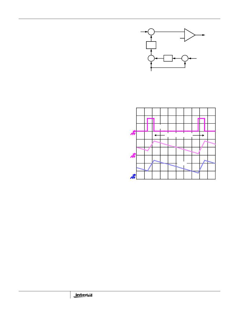
�FIGURE� 4.� CHANNEL-1� PWM� FUNCTION� AND�
�CURRENT-BALANCE� ADJUSTMENT�
�The� filtered� error� signal� modifies� the� pulse� width�
�commanded� by� V� COMP� to� correct� any� unbalance� and� force�
�I� ER� toward� zero.� The� same� method� for� error� signal�
�correction� is� applied� to� each� active� channel.�
�V� APA� (� TRIP� )� =� R� APA� ?� 100� � 10�
�–� 6�
�(EQ.� 3)�
�Number� of� Active� Channels�
�The� default� number� of� active� channels� on� the� ISL6313� is� two�
�for� 2-phase� operation.� If� single� phase� operation� is� desired�
�the� ISEN2-� pin� should� be� tied� to� the� VCC� pin.� This� will�
�disable� Channel� 2,� so� only� Channel� 1� will� fire.� In� single�
�phase� operation� all� of� the� Channel� 2� pins� should� be� left�
�unconnected� including� the� PHASE2,� LGATE2,� UGATE2,�
�BOOT2,� and� ISEN2+� pins.�
�Channel-Current� Balance�
�One� important� benefit� of� multi-phase� operation� is� the� thermal�
�advantage� gained� by� distributing� the� dissipated� heat� over�
�multiple� devices� and� greater� area.� By� doing� this� the� designer�
�avoids� the� complexity� of� driving� parallel� MOSFETs� and� the�
�expense� of� using� expensive� heat� sinks� and� exotic� magnetic�
�materials.�
�In� order� to� realize� the� thermal� advantage,� it� is� important� that�
�each� channel� in� a� multi-phase� converter� be� controlled� to�
�carry� equal� amounts� of� current� at� any� load� level.� To� achieve�
�this,� the� currents� through� each� channel� must� be� sensed�
�continuously� every� switching� cycle.� The� sensed� currents,� I� n� ,�
�from� each� active� channel� are� summed� together� and� divided�
�by� the� number� of� active� channels.� The� resulting� cycle�
�average� current,� I� AVG� ,� provides� a� measure� of� the� total�
�load-current� demand� on� the� converter� during� each� switching�
�cycle.� Channel-current� balance� is� achieved� by� comparing�
�the� sensed� current� of� each� channel� to� the� cycle� average�
�current,� and� making� the� proper� adjustment� to� each� channel�
�pulse� width� based� on� the� error.� Intersil’s� patented�
�current-balance� method� is� illustrated� in� Figure� 4,� with� error�
�correction� for� Channel� 1� represented.� In� the� figure,� the� cycle�
�average� current,� I� AVG� ,� is� compared� with� the� Channel� 1�
�sensed� current,� I� 1� ,� to� create� an� error� signal� I� ER� .�
�12�
�PWM�
�SWITCHING� PERIOD�
�I� L�
�I� SEN�
�TIME�
�FIGURE� 5.� CONTINUOUS� CURRENT� SAMPLING�
�Continuous� Current� Sensing�
�In� order� to� realize� proper� current-balance,� the� currents� in�
�each� channel� are� sensed� continuously� every� switching�
�cycle.� During� this� time� the� current-sense� amplifier� uses� the�
�ISEN� inputs� to� reproduce� a� signal� proportional� to� the�
�inductor� current,� I� L� .� This� sensed� current,� I� SEN� ,� is� simply� a�
�scaled� version� of� the� inductor� current.�
�The� ISL6313� supports� inductor� DCR� current� sensing� to�
�continuously� sense� each� channel’s� current� for�
�channel-current� balance.� The� internal� circuitry,� shown� in�
�Figure� 6� represents� channel� n� of� an� N-Channel� converter.�
�This� circuitry� is� repeated� for� each� channel� in� the� converter,�
�but� may� not� be� active� depending� on� how� many� channels� are�
�operating.�
�FN6448.2�
�September� 2,� 2008�
�相关PDF资料 |
PDF描述 |
|---|---|
| ESM28DSAN | CONN EDGECARD 56POS R/A .156 SLD |
| LT1521IST-3.3#PBF | IC REG LDO 3.3V .3A SOT223-3 |
| RSM18DSUS | CONN EDGECARD 36POS DIP .156 SLD |
| 450MXG220MEFCSN25X40 | CAP ALUM 220UF 450V 20% SNAP-IN |
| ESM28DSAH | CONN EDGECARD 56POS R/A .156 SLD |
相关代理商/技术参数 |
参数描述 |
|---|---|
| ISL6314CRZ | 功能描述:电压模式 PWM 控制器 1-PH PWM CNTRLR W/1 INTEGRTD DRVRS 32LD RoHS:否 制造商:Texas Instruments 输出端数量:1 拓扑结构:Buck 输出电压:34 V 输出电流: 开关频率: 工作电源电压:4.5 V to 5.5 V 电源电流:600 uA 最大工作温度:+ 125 C 最小工作温度:- 40 C 封装 / 箱体:WSON-8 封装:Reel |
| ISL6314CRZ-T | 功能描述:IC CTRLR PWM 1PHASE BUCK 32-QFN RoHS:是 类别:集成电路 (IC) >> PMIC - 稳压器 - 专用型 系列:- 标准包装:43 系列:- 应用:控制器,Intel VR11 输入电压:5 V ~ 12 V 输出数:1 输出电压:0.5 V ~ 1.6 V 工作温度:-40°C ~ 85°C 安装类型:表面贴装 封装/外壳:48-VFQFN 裸露焊盘 供应商设备封装:48-QFN(7x7) 包装:管件 |
| ISL6314CRZ-TR5453 | 制造商:Intersil Corporation 功能描述:STD. ISL6314CRZ-T W/GOLD BOND WIRE ONLY T&R - Tape and Reel |
| ISL6314CRZ-TS2568 | 制造商:Intersil Corporation 功能描述:- Tape and Reel |
| ISL6314IRZ | 功能描述:IC CTRLR PWM 1PHASE BUCK 32-QFN RoHS:是 类别:集成电路 (IC) >> PMIC - 稳压器 - 专用型 系列:- 标准包装:43 系列:- 应用:控制器,Intel VR11 输入电压:5 V ~ 12 V 输出数:1 输出电压:0.5 V ~ 1.6 V 工作温度:-40°C ~ 85°C 安装类型:表面贴装 封装/外壳:48-VFQFN 裸露焊盘 供应商设备封装:48-QFN(7x7) 包装:管件 |
发布紧急采购,3分钟左右您将得到回复。