参数资料
| 型号: | ISL6313IRZ-T |
| 厂商: | Intersil |
| 文件页数: | 20/33页 |
| 文件大小: | 0K |
| 描述: | IC CTRLR PWM 2PHASE BUCK 36-QFN |
| 产品培训模块: | Solutions for Industrial Control Applications |
| 标准包装: | 4,000 |
| 应用: | 控制器,Intel VR11,AMD CPU |
| 输入电压: | 5 V ~ 12 V |
| 输出数: | 1 |
| 输出电压: | 0.5 V ~ 1.6 V |
| 工作温度: | -40°C ~ 85°C |
| 安装类型: | 表面贴装 |
| 封装/外壳: | 36-WFQFN 裸露焊盘 |
| 供应商设备封装: | 36-TQFN 裸露焊盘(6x6) |
| 包装: | 带卷 (TR) |
第1页第2页第3页第4页第5页第6页第7页第8页第9页第10页第11页第12页第13页第14页第15页第16页第17页第18页第19页当前第20页第21页第22页第23页第24页第25页第26页第27页第28页第29页第30页第31页第32页第33页
�� �
�
�ISL6313�
�Advanced� Adaptive� Zero� Shoot-Through� Deadtime�
�Control� (Patent� Pending)�
�The� integrated� drivers� incorporate� a� unique� adaptive� deadtime�
�The� bootstrap� capacitor� must� have� a� maximum� voltage�
�rating� above� PVCC� +� 4V� and� its� capacitance� value� can� be�
�chosen� from� Equation� 18:�
�C� BOOT_CAP� ≥� --------------------------------------�
�control� technique� to� minimize� deadtime,� resulting� in� high�
�efficiency� from� the� reduced� freewheeling� time� of� the� lower�
�MOSFET� body-diode� conduction,� and� to� prevent� the� upper� and�
�Q� GATE�
�Δ� V� BOOT_CAP�
�(EQ.� 18)�
�Q� GATE� =� ----------------------------------� ?� N� Q1�
�lower� MOSFETs� from� conducting� simultaneously.� This� is�
�accomplished� by� ensuring� either� rising� gate� turns� on� its�
�MOSFET� with� minimum� and� sufficient� delay� after� the� other� has�
�turned� off.�
�During� turn-off� of� the� lower� MOSFET,� the� PHASE� voltage� is�
�monitored� until� it� reaches� a� -0.3V/+0.8V� (forward/reverse�
�inductor� current).� At� this� time� the� UGATE� is� released� to� rise.� An�
�auto-zero� comparator� is� used� to� correct� the� r� DS(ON)� drop� in� the�
�phase� voltage� preventing� false� detection� of� the� -0.3V� phase�
�level� during� r� DS(ON)� conduction� period.� In� the� case� of� zero�
�current,� the� UGATE� is� released� after� 35ns� delay� of� the� LGATE�
�dropping� below� 0.5V.� When� LGATE� first� begins� to� transition�
�low,� this� quick� transition� can� disturb� the� PHASE� node� and�
�cause� a� false� trip,� so� there� is� 20ns� of� blanking� time� once�
�LGATE� falls� until� PHASE� is� monitored.�
�Once� the� PHASE� is� high,� the� advanced� adaptive�
�shoot-through� circuitry� monitors� the� PHASE� and� UGATE�
�voltages� during� a� PWM� falling� edge� and� the� subsequent�
�UGATE� turn-off.� If� either� the� UGATE� falls� to� less� than� 1.75V�
�above� the� PHASE� or� the� PHASE� falls� to� less� than� +0.8V,� the�
�LGATE� is� released� to� turn-on.�
�Q� G1� ?� PVCC�
�V� GS1�
�where� Q� G1� is� the� amount� of� gate� charge� per� upper� MOSFET�
�at� V� GS1� gate-source� voltage� and� N� Q1� is� the� number� of�
�control� MOSFETs.� The� Δ� V� BOOT_CAP� term� is� defined� as� the�
�allowable� droop� in� the� rail� of� the� upper� gate� drive.�
�Gate� Drive� Voltage� Versatility�
�The� ISL6313� provides� the� user� flexibility� in� choosing� the�
�gate� drive� voltage� for� efficiency� optimization.� The� controller�
�ties� the� upper� and� lower� drive� rails� together.� Simply� applying�
�a� voltage� from� 5V� up� to� 12V� on� PVCC� sets� both� gate� drive�
�rail� voltages� simultaneously.�
�Initialization�
�Prior� to� initialization,� proper� conditions� must� exist� on� the� EN,�
�VCC,� PVCC� and� the� VID� pins.� When� the� conditions� are� met,�
�the� controller� begins� soft-start.� Once� the� output� voltage� is�
�within� the� proper� window� of� operation,� the� controller� asserts�
�PGOOD.�
�Internal� Bootstrap� Device�
�All� three� integrated� drivers� feature� an� internal� bootstrap�
�schottky� diode.� Simply� adding� an� external� capacitor� across�
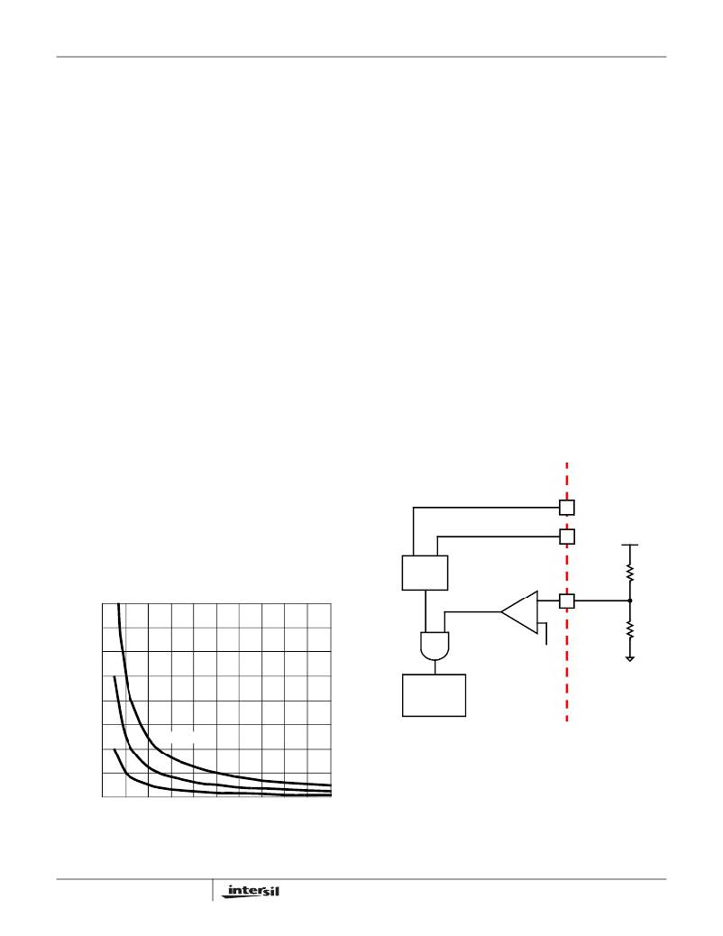
�ISL6313� INTERNAL� CIRCUIT�
�EXTERNAL� CIRCUIT�
�VCC�
�the� BOOT� and� PHASE� pins� completes� the� bootstrap� circuit.�
�The� bootstrap� function� is� also� designed� to� prevent� the�
�PVCC�
�+� 12� V�
�bootstrap� capacitor� from� overcharging� due� to� the� large�
�negative� swing� at� the� PHASE� node.� This� reduces� voltage�
�stress� on� the� boot� to� phase� pins.�
�1.6�
�1.4�
�POR�
�CIRCUIT�
�ENABLE�
�COMPARATOR�
�+�
�-�
�EN�
�10.7k� Ω�
�1.40k� Ω�
�1.2�
�1.0�
�0.8�
�0.6�
�0.4�
�Q� GATE� = 100nC�
�50nC�
�0.85V�
�SOFT-START�
�AND�
�FAULT� LOGIC�
�FIGURE� 12.� POWER� SEQUENCING� USING�
�THRESHOLD-SENSITIVE� ENABLE� (EN)�
�FUNCTION�
�0.2�
�20nC�
�Enable� and� Disable�
�0.0�
�0.0�
�0.1�
�0.2�
�0.3�
�0.4�
�0.5�
�0.6�
�0.7�
�0.8�
�0.9�
�1.0�
�While� in� shutdown� mode,� the� LGATE� and� UGATE� signals�
�Δ� V� BOOT_CAP� (V)�
�FIGURE� 11.� BOOTSTRAP� CAPACITANCE� vs� BOOT� RIPPLE�
�VOLTAGE�
�20�
�are� held� low� to� assure� the� MOSFETs� remain� off.� The�
�following� input� conditions� must� be� met� (for� both� Intel� and�
�AMD� modes� of� operation)� before� the� ISL6313� is� released�
�FN6448.2�
�September� 2,� 2008�
�相关PDF资料 |
PDF描述 |
|---|---|
| ESM28DSAN | CONN EDGECARD 56POS R/A .156 SLD |
| LT1521IST-3.3#PBF | IC REG LDO 3.3V .3A SOT223-3 |
| RSM18DSUS | CONN EDGECARD 36POS DIP .156 SLD |
| 450MXG220MEFCSN25X40 | CAP ALUM 220UF 450V 20% SNAP-IN |
| ESM28DSAH | CONN EDGECARD 56POS R/A .156 SLD |
相关代理商/技术参数 |
参数描述 |
|---|---|
| ISL6314CRZ | 功能描述:电压模式 PWM 控制器 1-PH PWM CNTRLR W/1 INTEGRTD DRVRS 32LD RoHS:否 制造商:Texas Instruments 输出端数量:1 拓扑结构:Buck 输出电压:34 V 输出电流: 开关频率: 工作电源电压:4.5 V to 5.5 V 电源电流:600 uA 最大工作温度:+ 125 C 最小工作温度:- 40 C 封装 / 箱体:WSON-8 封装:Reel |
| ISL6314CRZ-T | 功能描述:IC CTRLR PWM 1PHASE BUCK 32-QFN RoHS:是 类别:集成电路 (IC) >> PMIC - 稳压器 - 专用型 系列:- 标准包装:43 系列:- 应用:控制器,Intel VR11 输入电压:5 V ~ 12 V 输出数:1 输出电压:0.5 V ~ 1.6 V 工作温度:-40°C ~ 85°C 安装类型:表面贴装 封装/外壳:48-VFQFN 裸露焊盘 供应商设备封装:48-QFN(7x7) 包装:管件 |
| ISL6314CRZ-TR5453 | 制造商:Intersil Corporation 功能描述:STD. ISL6314CRZ-T W/GOLD BOND WIRE ONLY T&R - Tape and Reel |
| ISL6314CRZ-TS2568 | 制造商:Intersil Corporation 功能描述:- Tape and Reel |
| ISL6314IRZ | 功能描述:IC CTRLR PWM 1PHASE BUCK 32-QFN RoHS:是 类别:集成电路 (IC) >> PMIC - 稳压器 - 专用型 系列:- 标准包装:43 系列:- 应用:控制器,Intel VR11 输入电压:5 V ~ 12 V 输出数:1 输出电压:0.5 V ~ 1.6 V 工作温度:-40°C ~ 85°C 安装类型:表面贴装 封装/外壳:48-VFQFN 裸露焊盘 供应商设备封装:48-QFN(7x7) 包装:管件 |
发布紧急采购,3分钟左右您将得到回复。