参数资料
| 型号: | ISL6323BCRZ |
| 厂商: | Intersil |
| 文件页数: | 29/36页 |
| 文件大小: | 0K |
| 描述: | IC PWM CTRLR SYNC BUCK DL 48QFN |
| 标准包装: | 43 |
| 应用: | 控制器,AMD SVI |
| 输入电压: | 5 V ~ 12 V |
| 输出数: | 2 |
| 输出电压: | 最高 2V |
| 工作温度: | 0°C ~ 70°C |
| 安装类型: | 表面贴装 |
| 封装/外壳: | 48-VFQFN 裸露焊盘 |
| 供应商设备封装: | 48-QFN(7x7) |
| 包装: | 管件 |
第1页第2页第3页第4页第5页第6页第7页第8页第9页第10页第11页第12页第13页第14页第15页第16页第17页第18页第19页第20页第21页第22页第23页第24页第25页第26页第27页第28页当前第29页第30页第31页第32页第33页第34页第35页第36页
�� �
�
�ISL6323B�
�CASE� 3�
�Core� inductors� must� be� set� up� with� proper� gain.� This� gain�
�I� Core�
�?� DCR� NB� =� --------------------------� ?� DCR� Core�
�I� NB�
�MAX�
�MAX�
�N�
�(EQ.� 43)�
�will� represent� the� variable� “K”� in� all� equations.� It� is� also� very�
�important� that� the� R� SET� resistor� be� tied� between� the� RSET�
�In� Case� 3,� the� DC� voltage� across� the� North� Bridge� inductor�
�at� full� load� is� equal� to� the� DC� voltage� across� a� single� phase�
�of� the� Core� regulator� while� at� full� load.� Here,� the� full� scale�
�pin� and� the� VCC� pin� of� the� ISL6323.�
�Inductor� DCR� Current� Sensing� Component� Fine�
�Tuning�
�DC� inductor� voltages� for� both� North� Bridge� and� Core� will� be�
�impressed� across� the� ISEN� pins� without� any� gain.� So,� the� R� 2�
�V� IN�
�I�
�L�
�n�
�resistors� for� the� Core� and� North� Bridge� inductor� RC� filters�
�are� left� unpopulated� and� K� =� 1� for� both� regulators.�
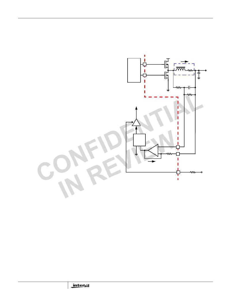
�MOSFET�
�UGATE(n)�
�L�
�DCR�
�V� OUT�
�For� this� Case,� it� is� recommended� that� the� overcurrent� trip�
�point� for� the� North� Bridge� regulator� be� equal� to� the�
�DRIVER�
�LGATE(n)�
�INDUCTOR�
�V� L� (s)�
�C� OUT�
�overcurrent� trip� point� for� the� Core� regulator� divided� by� the�
�V� C� (s)�
�number� of� core� phases.�
�1.� Choose� a� capacitor� value� for� the� North� Bridge� RC� filter.� A�
�0.1μF� capacitor� is� a� recommended� starting� point.�
�2.� Calculate� the� value� for� the� North� Bridge� resistor� R� 1� :�
�ISL6323B� INTERNAL� CIRCUIT�
�R� 1�
�C�
�R� 2�
�L� NB�
�DCR� NB� ?� C� NB�
�R� 1�
�NB�
�=� --------------------------------------�
�(EQ.� 44)�
�I� n�
�K� I� =� -----------------�
�3.� Choose� a� capacitor� value� for� the� Core� RC� filter.� A� 0.1μF�
�capacitor� is� a� recommended� starting� point.�
�5.� Calculate� the� value� for� the� Core� resistor� R� 1� :�
�K� I�
�SAMPLE�
�40k� Ω�
�R� SET�
�L� Core�
�DCR� Core� ?� C� Core�
�R� 1�
�Core�
�=� ------------------------------------------------�
�(EQ.� 45)�
�+�
�-�
�V� C� (s)�
�ISENn-�
�R� SET� =� ----------� ?� ---------------------------------------� ?� ?� I� OCP�
�400� DCR� CORE� ?� K� ?� V� IN� –� V� CORE� V� CORE� ?�
�+� -------------------------------------------� ?� --------------------� ?�
�2� ?� L� CORE� ?� f� SW�
�?�
�V� IN� ?�
�6.� Calculate� the� value� for� the� R� SET� resistor� using� Equation� 46:�
�3� 100� μ� A� ?� N� CORE�
�I� SEN�
�R� ISEN�
�2.4k� Ω�
�ISENn+�
�RSET�
�Where:� K� =� 1�
�(EQ.� 46)�
�R� SET�
�VCC�
�7.� Calculate� the� OCP� trip� point� for� the� North� Bridge� regulator�
�using� Equation� 47.� If� the� OCP� trip� point� is� higher� than�
�desired,� then� the� component� values� must� be� recalculated�
�utilizing� Case� 1.� If� the� OCP� trip� point� is� lower� than� desired,�
�then� the� component� values� must� be� recalculated� utilized�
�Case� 2.�
�FIGURE� 20.� DCR� SENSING� CONFIGURATION�
�Due� to� errors� in� the� inductance� and/or� DCR� it� may� be�
�necessary� to� adjust� the� value� of� R� 1� and� R� 2� to� match� the� time�
�constants� correctly.� The� effects� of� time� constant� mismatch�
�can� be� seen� in� the� form� of� droop� overshoot� or� undershoot�
�=� 100� μ� A� ?� ---------------------� ?� ?� ----------� ?� R� SET� ?� +� ----------------------------------� ?� -----------�
�DCR� NB� ?� 400�
�2� ?� L� NB� ?� f� SW� V� IN�
�I� OCP�
�NB�
�?�
�1� 3� V� IN� –� V� NB� V� NB�
�during� the� initial� load� transient� spike,� as� shown� in� Figure� 21.�
�Follow� the� steps� below� to� ensure� the� R-C� and� inductor�
�(EQ.� 47)�
�NOTE:� The� values� of� R� SET� must� be� greater� than� 20k� Ω� and�
�less� than� 80k� Ω� .� For� all� of� the� 3� cases,� if� the� calculated� value�
�of� R� SET� is� less� than� 20k� Ω� ,� then� either� the� OCP� trip� point�
�needs� to� be� increased� or� the� inductor� must� be� changed� to� an�
�inductor� with� higher� DCR.� If� the� R� SET� resistor� is� greater� than�
�80k� Ω� ,� then� a� value� of� R� SET� that� is� less� than� 80k� Ω� must� be�
�chosen� and� a� resistor� divider� across� both� North� Bridge� and�
�29�
�L/DCR� time� constants� are� matched� accurately.�
�1.� If� the� regulator� is� not� utilizing� droop,� modify� the� circuit� by�
�placing� the� frequency� set� resistor� between� FS� and�
�Ground� for� the� duration� of� this� procedure.�
�2.� Capture� a� transient� event� with� the� oscilloscope� set� to�
�about� L/DCR/2� (sec/div).� For� example,� with� L� =� 1μH� and�
�DCR� =� 1m� Ω� ,� set� the� oscilloscope� to� 500μs/div.�
�3.� Record� Δ� V1� and� Δ� V2� as� shown� in� Figure� 21.�
�FN6879.1�
�May� 12,� 2010�
�相关PDF资料 |
PDF描述 |
|---|---|
| RCA18DTMT | CONN EDGECARD 36POS R/A .125 SLD |
| ISL6323ACRZ | IC PWM CTRLR SYNC BUCK DL 48QFN |
| LD6806CX4/25H,315 | IC REG LDO 2.5V .2A 4WLCSP |
| 420USC390MEFCSN30X40 | CAP ALUM 390UF 420V 20% SNAP-IN |
| 2256-19L | POWER CHOKE 33UH MOLDED AXIAL |
相关代理商/技术参数 |
参数描述 |
|---|---|
| ISL6323BCRZR5381 | 制造商:Intersil Corporation 功能描述:4+1 PHASE CONT. FOR CORE+NORTHBRIDGE, 2 PHASE PSI, 3.4MHZ SV - Rail/Tube 制造商:Intersil Corporation 功能描述:IC PWM CTRLR SYNC BUCK DL 48QFN 制造商:Intersil 功能描述:4+1 PHS CONT CORE + NORTHBRDG PROG |
| ISL6323BCRZ-T | 功能描述:IC PWM CTRLR SYNC BUCK DL 48QFN RoHS:是 类别:集成电路 (IC) >> PMIC - 稳压器 - 专用型 系列:- 标准包装:43 系列:- 应用:控制器,Intel VR11 输入电压:5 V ~ 12 V 输出数:1 输出电压:0.5 V ~ 1.6 V 工作温度:-40°C ~ 85°C 安装类型:表面贴装 封装/外壳:48-VFQFN 裸露焊盘 供应商设备封装:48-QFN(7x7) 包装:管件 |
| ISL6323BCRZ-TR5381 | 制造商:Intersil Corporation 功能描述:4+1 PHASE CONT. FOR CORE+NORTHBRIDGE, 2 PHASE PSI, 3.4MHZ S - Tape and Reel 制造商:Intersil Corporation 功能描述:IC PWM CTRLR SYNC BUCK DL 48QFN 制造商:Intersil 功能描述:4+1 PHS CONT CORE + NORTHBRDG PROG |
| ISL6323BCRZ-TR5453 | 制造商:Intersil Corporation 功能描述:STD. ISL6323BCRZ-T WITH GOLD BOND WIRE ONLY, T&R - Tape and Reel |
| ISL6323BIRZ | 功能描述:IC PWM CTRLR SYNC BUCK DL 48QFN RoHS:是 类别:集成电路 (IC) >> PMIC - 稳压器 - 专用型 系列:- 标准包装:43 系列:- 应用:控制器,Intel VR11 输入电压:5 V ~ 12 V 输出数:1 输出电压:0.5 V ~ 1.6 V 工作温度:-40°C ~ 85°C 安装类型:表面贴装 封装/外壳:48-VFQFN 裸露焊盘 供应商设备封装:48-QFN(7x7) 包装:管件 |
发布紧急采购,3分钟左右您将得到回复。