- 您现在的位置:买卖IC网 > PDF目录80464 > M38039GCHWG 8-BIT, MROM, 8.4 MHz, MICROCONTROLLER, PBGA64 PDF资料下载
参数资料
| 型号: | M38039GCHWG |
| 元件分类: | 微控制器/微处理器 |
| 英文描述: | 8-BIT, MROM, 8.4 MHz, MICROCONTROLLER, PBGA64 |
| 封装: | 6 X 6 MM, 0.65 PITCH, FLGA-64 |
| 文件页数: | 73/103页 |
| 文件大小: | 1412K |
| 代理商: | M38039GCHWG |
第1页第2页第3页第4页第5页第6页第7页第8页第9页第10页第11页第12页第13页第14页第15页第16页第17页第18页第19页第20页第21页第22页第23页第24页第25页第26页第27页第28页第29页第30页第31页第32页第33页第34页第35页第36页第37页第38页第39页第40页第41页第42页第43页第44页第45页第46页第47页第48页第49页第50页第51页第52页第53页第54页第55页第56页第57页第58页第59页第60页第61页第62页第63页第64页第65页第66页第67页第68页第69页第70页第71页第72页当前第73页第74页第75页第76页第77页第78页第79页第80页第81页第82页第83页第84页第85页第86页第87页第88页第89页第90页第91页第92页第93页第94页第95页第96页第97页第98页第99页第100页第101页第102页第103页
REJ03B0166-0113 Rev.1.13
Aug 21, 2009
Page 71 of 100
3803 Group (Spec.H QzROM version)
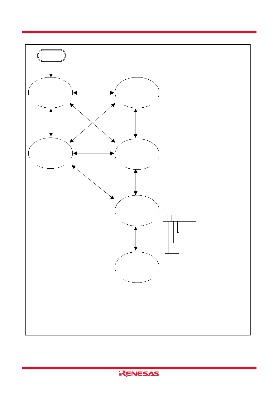
Fig 67. State transitions of system clock
CM4 : Port XC switch bit
0 : I/O port function (stop oscillating)
1 : XCIN-XCOUT oscillating function
CM5 : Main clock (XIN-XOUT) stop bit
0 : Operating
1 : Stopped
CM7, CM6: Main clock division ratio selection bit
b7 b6
00 :
φ = f(XIN)/2 (High-speed mode)
01 :
φ = f(XIN)/8 (Middle-speed mode)
10 :
φ = f(XCIN)/2 (Low-speed mode)
1 1 : Not available
Reset
CM
4
“1
”←→
”0”
C
M
4
“0
”
←
→
”1
”
C
M
6
“1
”
←
→
”0
”
C
M
4
“1
”←
→
”0
”
C
M
6
“1
”←
→
”0
”
CM
7
“1
”←→
”0
”
CM
4
“1
”←→
”0
”
CM
5
“1
”←→
”0
”
CM6
“1”
←→”0”
CM6
“1”
←→”0”
CPU mode register
(CPUM : address 003B16)
b7
b4
C
M
7
“0
”
←
→
”1
”
C
M
6
“1
”
←
→
”0”
High-speed mode
(f(
φ) = 4 MHz)
CM7=0
CM6=0
CM5=0 (8 MHz oscillating)
CM4=0 (32 kHz stopped)
High-speed mode
(f(
φ) = 4 MHz)
CM7=0
CM6=0
CM5=0 (8 MHz oscillating)
CM4=1 (32 kHz oscillating)
Notes1: Switch the mode by the allows shown between the mode blocks. (Do not switch between the modes directly without an allow.)
2: The all modes can be switched to the stop mode or the wait mode and return to the source mode when the stop mode or the
wait mode is ended.
3: Timer operates in the wait mode.
4: When the stop mode is ended, a delay of approximately 1 ms occurs by connecting prescaler 12 and Timer 1 in middle/high-
speed mode.
5: When the stop mode is ended, a delay of approximately 0.25 s occurs by Timer 1 and Timer 2 in low-speed mode.
6: Wait until oscillation stabilizes after oscillating the main clock X IN before the switching from the low-speed mode to middle/
high-speed mode.
7: The example assumes that 8 MHz is being applied to the XIN pin and 32 kHz to the XCIN pin.
φ indicates the internal clock.
Middle-speed mode
(f(
φ) = 1 MHz)
CM7=0
CM6=1
CM5=0 (8 MHz oscillating)
CM4=0 (32 kHz stopped)
Middle-speed mode
(f(
φ) = 1 MHz)
CM7=0
CM6=1
CM5=0 (8 MHz oscillating)
CM4=1 (32 kHz oscillating)
Low-speed mode
(f(
φ) = 16 kHz)
CM7=1
CM6=0
CM5=0 (8 MHz oscillating)
CM4=1 (32 kHz oscillating)
Low-speed mode
(f(
φ) = 16 kHz)
CM7=1
CM6=0
CM5=1 (8 MHz stopped)
CM4=1 (32 kHz oscillating)
相关PDF资料 |
PDF描述 |
|---|---|
| MSP430F2350IYFF | 16-BIT, FLASH, 16 MHz, RISC MICROCONTROLLER, PBGA49 |
| MK1707D | 108 MHz, OTHER CLOCK GENERATOR, PDSO8 |
| MPC8347ZUAGFA | 32-BIT, 400 MHz, MICROPROCESSOR, PBGA672 |
| M30302GGPGP | 16-BIT, OTPROM, 16 MHz, MICROCONTROLLER, PQFP100 |
| MC3S12HN64J3CAA | 16-BIT, MROM, 25 MHz, MICROCONTROLLER, PQFP80 |
相关代理商/技术参数 |
参数描述 |
|---|---|
| M38049FFFP#U0 | 制造商:Renesas Electronics Corporation 功能描述: |
| M38049FFLHP#U0 | 制造商:Renesas Electronics Corporation 功能描述: |
| M38049RLSS | 功能描述:DEV EMULATOR CHIP RAM 2KB 64SDIP RoHS:否 类别:编程器,开发系统 >> 内电路编程器、仿真器以及调试器 系列:- 产品变化通告:Development Systems Discontinuation 19/Jul/2010 标准包装:1 系列:* 类型:* 适用于相关产品:* 所含物品:* |
| M3806 | 功能描述:电缆固定件和配件 LTSCG 625 BLACK RoHS:否 制造商:Heyco 类型:Cable Grips, Liquid Tight 材料:Nylon 颜色:Black 安装方法:Cable 最大光束直径:11.4 mm 抗拉强度: |
| M3806 BK001 | 制造商:Alpha Wire Company 功能描述:CBL 8COND 18AWG BLK 1000' |
发布紧急采购,3分钟左右您将得到回复。