- 您现在的位置:买卖IC网 > PDF目录1841 > MAX1897ETP+T (Maxim Integrated Products)IC REG CTRLR BUCK PWM 20-TQFN PDF资料下载
参数资料
| 型号: | MAX1897ETP+T |
| 厂商: | Maxim Integrated Products |
| 文件页数: | 16/33页 |
| 文件大小: | 0K |
| 描述: | IC REG CTRLR BUCK PWM 20-TQFN |
| 标准包装: | 2,500 |
| 系列: | Quick-PWM™ |
| PWM 型: | 控制器 |
| 输出数: | 1 |
| 频率 - 最大: | 550kHz |
| 电源电压: | 4.5 V ~ 5.5 V |
| 降压: | 是 |
| 升压: | 无 |
| 回扫: | 无 |
| 反相: | 无 |
| 倍增器: | 无 |
| 除法器: | 无 |
| Cuk: | 无 |
| 隔离: | 无 |
| 工作温度: | 0°C ~ 85°C |
| 封装/外壳: | 20-WQFN 裸露焊盘 |
| 包装: | 带卷 (TR) |
第1页第2页第3页第4页第5页第6页第7页第8页第9页第10页第11页第12页第13页第14页第15页当前第16页第17页第18页第19页第20页第21页第22页第23页第24页第25页第26页第27页第28页第29页第30页第31页第32页第33页
�� �
�
�Quick-PWM� Slave� Controllers� for�
�Multiphase,� Step-Down� Supplies�
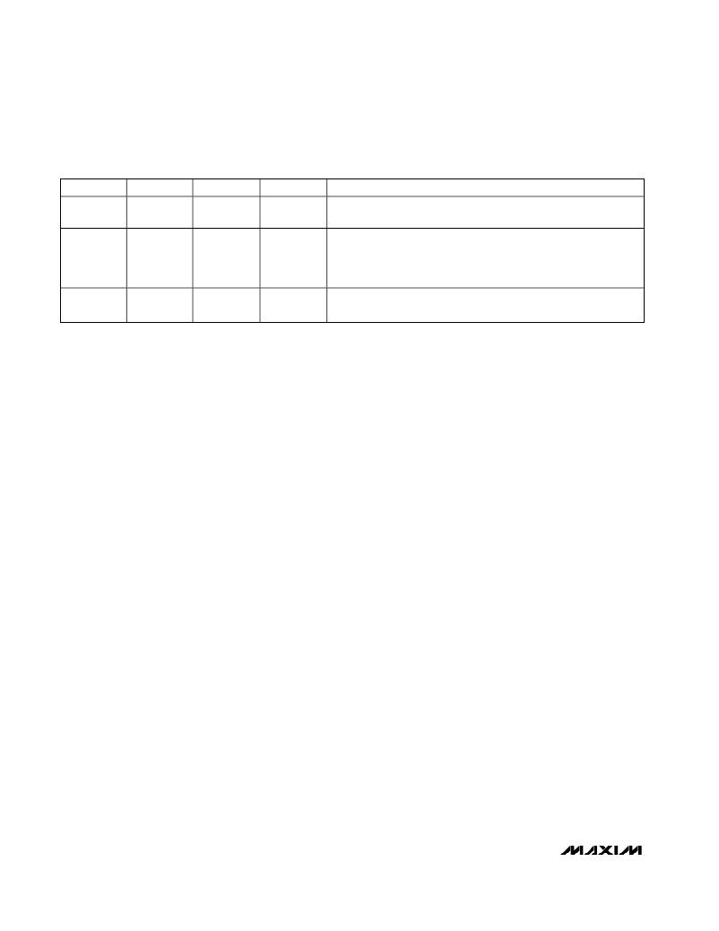
�Table� 4.� Operating� Mode� Truth� Table�
�SHDN�
�GND�
�ILIM�
�X�
�DL�
�High�
�MODE�
�Shutdown�
�COMMENTS�
�Micropower,� shutdown� mode� (I� CC� +I� DD� <� 1μA� typ).� DL� forced� high,�
�DH� forced� low,� and� the� PWM� controller� disabled.�
�Low-power,� standby� mode� (I� CC� +� I� DD� =� 20μA� typ).� DL� forced� high,�
�V� CC�
�GND�
�(<� 0.25V)�
�High�
�Standby�
�DH� forced� low,� and� the� PWM� controller� disabled.� However,� the� bias�
�and� fault� protection� circuitry� remain� active� so� the� MAX1887/MAX1897�
�can� continuously� monitor� the� ILIM� input.�
�V� CC�
�High�
�(>� 0.25V)�
�Switching�
�Normal�
�Operation�
�Low-noise,� fixed-frequency,� PWM� operation.� The� inductor� current�
�reverses� with� light� loads.�
�X� =� Don� ’� t� Care�
�Several� Quick-PWM� converters� that� may� be� used� as� the�
�master� controller� ramp� down� the� output� voltage� at� a�
�controlled� slew� rate� when� shut� down.� When� combined�
�with� these� master� controllers,� the� MAX1897� must� not� be�
�deactivated� until� the� output� voltage� is� fully� discharged.�
�Otherwise� the� slave� ’� s� low� side� switch� will� turn� on� while�
�the� master� is� still� attempting� to� regulate� the� output.� In�
�these� applications,� delay� the� shutdown� input� signal� to�
�the� MAX1897� or� permanently� connect� SHDN� to� V� CC�
�and� use� standby� mode� to� conserve� power� (see� the�
�Standby� Mode� section).�
�Standby� Mode�
�The� MAX1887/MAX1897� slave� controllers� enter� a� low-�
�power� standby� mode� when� the� ILIM� voltage� (V� ILIM� )�
�drops� below� 250mV� (Table� 4).� Similar� to� shutdown�
�mode,� standby� forces� DL� high,� pulls� DH� low,� and� dis-�
�ables� the� PWM� controller� to� inhibit� switching;� however,�
�the� bias� and� fault� protection� circuitry� remain� active� so�
�the� MAX1887/MAX1897� can� continuously� monitor� the�
�ILIM� input.� When� V� ILIM� is� driven� above� 250mV,� the�
�PWM� controller� is� enabled.�
�When� the� slave� controller� ’� s� current-limit� voltage� (V� ILIM� )�
�is� set� through� a� resistive� divider� between� the� master�
�controller� ’� s� reference� and� GND� (see� the� Current-Limit�
�Circuitry� section),� the� MAX1887/MAX1897� automatically�
�enters� low-power� standby� mode� when� the� master� con-�
�troller� shuts� down.� As� the� master� ’� s� reference� powers�
�down,� the� resistive� divider� pulls� ILIM� below� 250mV,�
�automatically� activating� the� MAX1887/MAX1897� ’� s� low-�
�power� standby� mode.�
�Current-Limit� Circuitry�
�When� the� master� ’� s� inductor� current� exceeds� its� valley�
�current� limit,� the� master� extends� its� off� time� by� forcing�
�DL� high� until� the� inductor� current� falls� below� the� current-�
�limit� threshold.� Without� a� transition� on� the� master� ’� s� low-�
�side� gate� driver,� the� slave� cannot� initiate� a� new� on-time�
�pulse� so� the� slave� ’� s� inductor� current� ramps� down� as�
�well,� maintaining� the� current� balance.� Therefore,� the�
�slave� ’� s� valley� current� limit� only� needs� to� protect� the�
�slave� controller� if� the� current-balance� circuitry� or� the�
�master� current� limit� fails.� The� slave� ’� s� ILIM� input� voltage�
�should� be� selected� to� properly� adjust� the� master� ’� s� cur-�
�rent-limit� threshold.�
�Dual-Mode� ILIM� Input�
�The� current-limit� input� (ILIM)� features� dual-mode� opera-�
�tion,� serving� as� both� the� standby� mode� control� input�
�and� the� current-limit� threshold� adjustment.� The� slave�
�controller� enters� a� low-power� standby� mode� when� the�
�ILIM� voltage� (V� ILIM� )� is� pulled� below� 250mV.� For� ILIM�
�voltages� from� 400mV� to� 1.5V,� the� current-limit� threshold�
�voltage� is� precisely� 0.1� ?� V� ILIM� .� The� current-limit� volt-�
�age� may� be� accurately� set� with� a� resistive� voltage-�
�divider� between� the� master� controller� ’� s� reference� and�
�GND,� allowing� the� MAX1887/MAX1897� to� automatically�
�enter� the� low-power� standby� mode.�
�Slave� Current� Limit�
�The� slave� current-limit� circuit� employs� a� unique� “� valley� ”�
�current-sensing� algorithm.� If� the� current-sense� signal� is�
�above� the� current-limit� threshold,� the� MAX1887/� MAX1897�
�will� not� initiate� a� new� cycle� (Figure� 3).� The� actual� peak�
�inductor� current� is� greater� than� the� current-limit� threshold�
�by� an� amount� equal� to� the� inductor� ripple� current.�
�Therefore,� the� exact� current-limit� characteristic� and� maxi-�
�mum� load� capability� are� a� function� of� the� current-limit�
�threshold,� inductor� value,� and� input� voltage.� The� reward�
�for� this� uncertainty� is� robust,� overcurrent� sensing.� When�
�combined� with� master� controllers� that� contain� output�
�undervoltage� protection� circuits,� this� current-limit� method�
�is� effective� in� almost� every� circumstance.�
�16�
�______________________________________________________________________________________�
�相关PDF资料 |
PDF描述 |
|---|---|
| MAX1898EUB42+T | IC CHARGER LI+ SNGL 10-UMAX |
| MAX1904ETJ+ | IC CNTRLR PWR SPLY LN 32-TQFN |
| MAX1917EEE+T | IC CNTRLR SYNC BUCK 16-QSOP |
| MAX1921EUT33+T | IC REG BUCK SYNC 3.3V SOT23-6 |
| MAX1922ESA+ | IC SW CUR LIMIT USB 8-SOIC |
相关代理商/技术参数 |
参数描述 |
|---|---|
| MAX1898EUB41 | 功能描述:电池管理 Linear Charger for 1-Cell Li+ Battery RoHS:否 制造商:Texas Instruments 电池类型:Li-Ion 输出电压:5 V 输出电流:4.5 A 工作电源电压:3.9 V to 17 V 最大工作温度:+ 85 C 最小工作温度:- 40 C 封装 / 箱体:VQFN-24 封装:Reel |
| MAX1898EUB41+ | 功能描述:电池管理 Linear Charger for 1-Cell Li+ Battery RoHS:否 制造商:Texas Instruments 电池类型:Li-Ion 输出电压:5 V 输出电流:4.5 A 工作电源电压:3.9 V to 17 V 最大工作温度:+ 85 C 最小工作温度:- 40 C 封装 / 箱体:VQFN-24 封装:Reel |
| MAX1898EUB41+T | 功能描述:电池管理 Linear Charger for 1-Cell Li+ Battery RoHS:否 制造商:Texas Instruments 电池类型:Li-Ion 输出电压:5 V 输出电流:4.5 A 工作电源电压:3.9 V to 17 V 最大工作温度:+ 85 C 最小工作温度:- 40 C 封装 / 箱体:VQFN-24 封装:Reel |
| MAX1898EUB41-T | 功能描述:电池管理 Linear Charger for 1-Cell Li+ Battery RoHS:否 制造商:Texas Instruments 电池类型:Li-Ion 输出电压:5 V 输出电流:4.5 A 工作电源电压:3.9 V to 17 V 最大工作温度:+ 85 C 最小工作温度:- 40 C 封装 / 箱体:VQFN-24 封装:Reel |
| MAX1898EUB42 | 功能描述:电池管理 Linear Charger for 1-Cell Li+ Battery RoHS:否 制造商:Texas Instruments 电池类型:Li-Ion 输出电压:5 V 输出电流:4.5 A 工作电源电压:3.9 V to 17 V 最大工作温度:+ 85 C 最小工作温度:- 40 C 封装 / 箱体:VQFN-24 封装:Reel |
发布紧急采购,3分钟左右您将得到回复。