- 您现在的位置:买卖IC网 > PDF目录69018 > MB86860 (FUJITSU LTD) 32-BIT, 200 MHz, RISC PROCESSOR, PBGA352 PDF资料下载
参数资料
| 型号: | MB86860 |
| 厂商: | FUJITSU LTD |
| 元件分类: | 微控制器/微处理器 |
| 英文描述: | 32-BIT, 200 MHz, RISC PROCESSOR, PBGA352 |
| 封装: | PLASTIC, BGA-352 |
| 文件页数: | 8/70页 |
| 文件大小: | 1395K |
| 代理商: | MB86860 |
第1页第2页第3页第4页第5页第6页第7页当前第8页第9页第10页第11页第12页第13页第14页第15页第16页第17页第18页第19页第20页第21页第22页第23页第24页第25页第26页第27页第28页第29页第30页第31页第32页第33页第34页第35页第36页第37页第38页第39页第40页第41页第42页第43页第44页第45页第46页第47页第48页第49页第50页第51页第52页第53页第54页第55页第56页第57页第58页第59页第60页第61页第62页第63页第64页第65页第66页第67页第68页第69页第70页
Specifications subject to changes without prior notice
17
MB86860 SPARClite
Note: When [WE] is “0”, READY# input from c w exterior is always valid.
count1
[CN1]
Specifies the number of waits for the first cycle of non-burst and burst
transfers. The number of waits is the value specified for this field + 1,
These bits are valid when [WE] is “1”.
count2
[CN2]
Specifies the number of waits for the 2nd cycle of burst transfers and
thereafter.
Thus when 0 is specified, it is 1 wait. These bits are valid
when [WE] is “1”.
single cycle
burst mode
[SCB]
If this bit is set to “1”, transfers from the 2nd cycle on of a burst transfer
are performed with 0wait.
This bit is valid when set to “1”. Thus this bit
should be set together with [WE].
parity enable
[PE]
Enables and disables Parity functions for access to the corresponding
CS# areas.
Note: When READY# returns in the same cycle as AS#, 0wait is set and when READY# returns in the next
cycle 1wait is set.
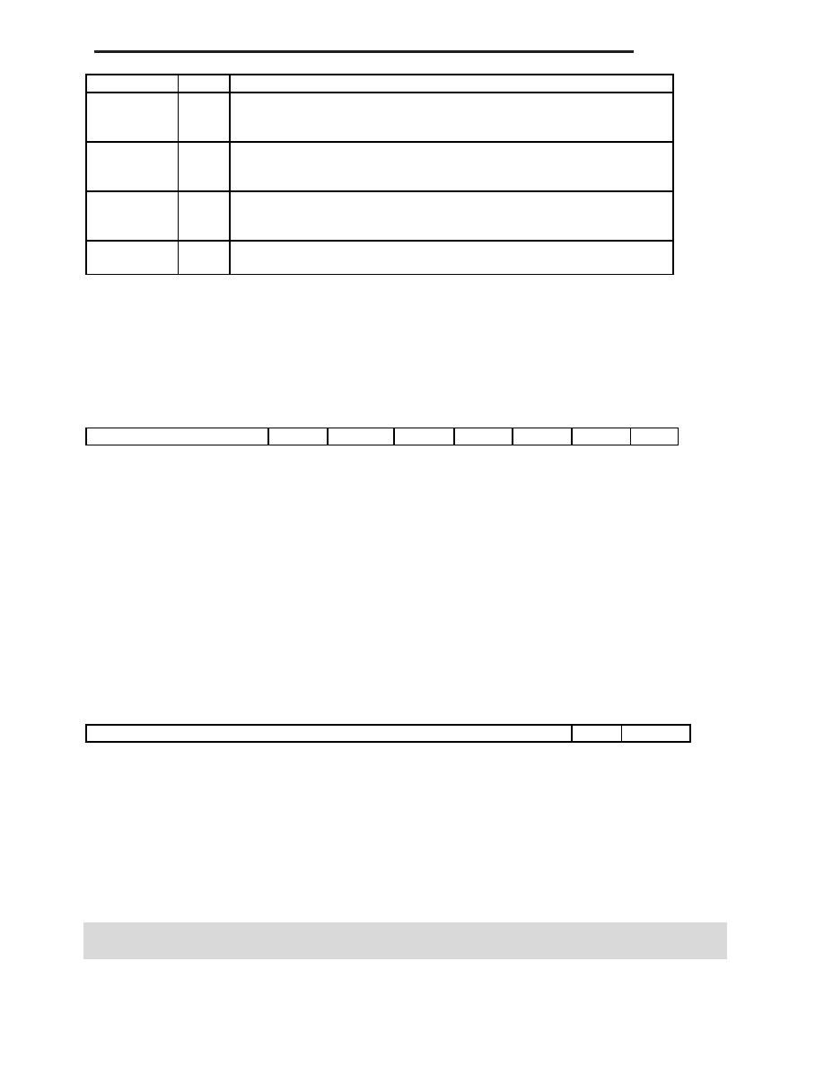
3.7. MXPEF : MEXC Parity Error Flag Register
Flags are set when a MEXC or parity error occurs during reads and writes. To clear a Flag, write “0” or perform a
reset.
31
7
6
5
4
3
2
1
0
Reserved
DMXRE
DMXWE
DPRE
Reserved
MXRE
MXWE
PRE
Address: 0x80000430 (ASI=04)
Reset State: 0x00000000
Figure 3-7 MXPEF Register
bit31-7:
Reserved
bit6:
DMA MEXC Read Error [DMXRE]
bit5:
DMA MEXC Write Error [DMXWE]
bit4:
DMA Parity Read Error [DPRE]
bit3:
Reserved
bit2:
CPU MEXC Read Error [MXRE]
bit1:
CPU MEXC Write Error [MXWE]
bit0:
CPU Parity Read Error [PRE]
3.8. MXPECR : MEXC Parity Error Control Register
Performs Return Mode Enable/Disable settings and Parity Check Odd/Even settings during the next Data Read from
the CPU when MEXC flags are set during data writes.
31
2
1
0
Reserved
PAR
MXWEE
Address: 0x80000438 (ASI=04)
Reset State: 0x00000000
Figure 3-10 MXPECR Register
bit31-2:
Reserved
bit1:
Parity bit (Odd Priority=0, Even Priority=1) [PAR]
bit2:
MEXC Write Error Enable [MXWEE]
相关PDF资料 |
PDF描述 |
|---|---|
| MB86931-20ZF-G | 32-BIT, 20 MHz, RISC MICROCONTROLLER, CQFP256 |
| MB86931-40ZF-G | 32-BIT, 40 MHz, RISC MICROCONTROLLER, CQFP256 |
| MB86933H-20PF-G | 32-BIT, 20 MHz, RISC PROCESSOR, PQFP160 |
| MB86934-60ZF | 32-BIT, 60 MHz, RISC PROCESSOR, CQFP256 |
| MB86936-25/50-PFV-G | 32-BIT, 25 MHz, RISC PROCESSOR, PQFP208 |
相关代理商/技术参数 |
参数描述 |
|---|---|
| MB86930-30ZF-G-BND | 制造商:FUJITSU 功能描述: |
| MB86941 | 制造商:FUJITSU 制造商全称:Fujitsu Component Limited. 功能描述:Peripheral LSI for SPARClite |
| MB86941PFV | 制造商:FUJITSU 制造商全称:Fujitsu Component Limited. 功能描述:Peripheral LSI for SPARClite |
| MB86942 | 制造商:FUJITSU 制造商全称:Fujitsu Component Limited. 功能描述:Peripheral LSI for SPARClite |
| MB86942PFV | 制造商:FUJITSU 制造商全称:Fujitsu Component Limited. 功能描述:Peripheral LSI for SPARClite |
发布紧急采购,3分钟左右您将得到回复。