- 您现在的位置:买卖IC网 > PDF目录45228 > MC68HC11E20VFN2 (FREESCALE SEMICONDUCTOR INC) 8-BIT, MROM, 2 MHz, MICROCONTROLLER, PQCC52 PDF资料下载
参数资料
| 型号: | MC68HC11E20VFN2 |
| 厂商: | FREESCALE SEMICONDUCTOR INC |
| 元件分类: | 微控制器/微处理器 |
| 英文描述: | 8-BIT, MROM, 2 MHz, MICROCONTROLLER, PQCC52 |
| 封装: | PLASTIC, LCC-52 |
| 文件页数: | 107/242页 |
| 文件大小: | 1672K |
| 代理商: | MC68HC11E20VFN2 |
第1页第2页第3页第4页第5页第6页第7页第8页第9页第10页第11页第12页第13页第14页第15页第16页第17页第18页第19页第20页第21页第22页第23页第24页第25页第26页第27页第28页第29页第30页第31页第32页第33页第34页第35页第36页第37页第38页第39页第40页第41页第42页第43页第44页第45页第46页第47页第48页第49页第50页第51页第52页第53页第54页第55页第56页第57页第58页第59页第60页第61页第62页第63页第64页第65页第66页第67页第68页第69页第70页第71页第72页第73页第74页第75页第76页第77页第78页第79页第80页第81页第82页第83页第84页第85页第86页第87页第88页第89页第90页第91页第92页第93页第94页第95页第96页第97页第98页第99页第100页第101页第102页第103页第104页第105页第106页当前第107页第108页第109页第110页第111页第112页第113页第114页第115页第116页第117页第118页第119页第120页第121页第122页第123页第124页第125页第126页第127页第128页第129页第130页第131页第132页第133页第134页第135页第136页第137页第138页第139页第140页第141页第142页第143页第144页第145页第146页第147页第148页第149页第150页第151页第152页第153页第154页第155页第156页第157页第158页第159页第160页第161页第162页第163页第164页第165页第166页第167页第168页第169页第170页第171页第172页第173页第174页第175页第176页第177页第178页第179页第180页第181页第182页第183页第184页第185页第186页第187页第188页第189页第190页第191页第192页第193页第194页第195页第196页第197页第198页第199页第200页第201页第202页第203页第204页第205页第206页第207页第208页第209页第210页第211页第212页第213页第214页第215页第216页第217页第218页第219页第220页第221页第222页第223页第224页第225页第226页第227页第228页第229页第230页第231页第232页第233页第234页第235页第236页第237页第238页第239页第240页第241页第242页
Bootstrap Mode Logic
M68HC11 Bootstrap Mode, Rev. 1.1
Freescale Semiconductor
195
Bootstrap mode can also be used to interactively calibrate critical analog sensors. Since this calibration
is done in the final assembled system, it can compensate for any errors in discrete interface circuitry and
cabling between the sensor and the analog inputs to the MCU. Note that this calibration routine is a
downloaded program that does not take up space in the normal application program.
Bootstrap Mode Logic
In the M68HC11 MCUs, very little logic is dedicated to the bootstrap mode. Consequently, this mode adds
almost no extra cost to the MCU system. The biggest piece of circuitry for bootstrap mode is the small
boot ROM. This ROM is 192 bytes in the original MC68HC11A8, but some of the newest members of the
M68HC11 Family, such as the MC68HC711K4, have as much as 448 bytes to accommodate added
features. Normally, this boot ROM is present in the memory map only when the MCU is reset in bootstrap
mode to prevent interference with the user’s normal memory space. The enable for this ROM is controlled
by the read boot ROM (RBOOT) control bit in the highest priority interrupt (HPRIO) register. The RBOOT
bit can be written by software whenever the MCU is in special test or special bootstrap modes; when the
MCU is in normal modes, RBOOT reverts to 0 and becomes a read-only bit. All other logic in the MCU
would be present whether or not there was a bootstrap mode.
Figure 1 shows the composite memory map of the MC68HC711E9 in its four basic modes of operation,
including bootstrap mode. The active mode is determined by the mode A (MDA) and special mode
(SMOD) control bits in the HPRIO control register. These control bits are in turn controlled by the state of
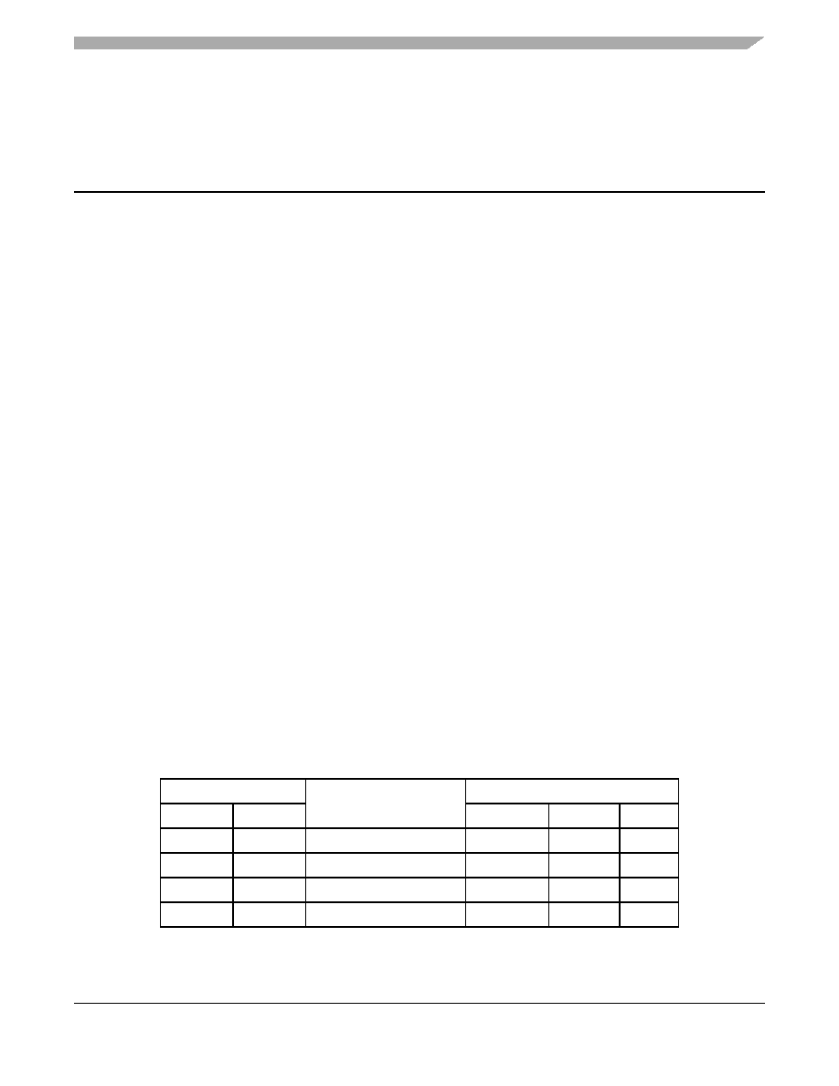
the mode A (MODA) and mode B (MODB) pins during reset. Table 1 shows the relationship between the
state of these pins during reset, the selected mode, and the state of the MDA, SMOD, and RBOOT control
bits. Refer to the composite memory map and information in Table 1 for the following discussion.
The MDA control bit is determined by the state of the MODA pin as the MCU leaves reset. MDA selects
between single-chip and expanded operating modes. When MDA is 0, a single-chip mode is selected,
either normal single-chip mode or special bootstrap mode. When MDA is 1, an expanded mode is
selected, either normal expanded mode or special test mode.
The SMOD control bit is determined by the inverted state of the MODB pin as the MCU leaves reset.
SMOD controls whether a normal mode or a special mode is selected. When SMOD is 0, one of the two
normal modes is selected, either normal single-chip mode or normal expanded mode. When SMOD is 1,
one of the two special modes is selected, either special bootstrap mode or special test mode. When either
special mode is in effect (SMOD = 1), certain privileges are in effect, for instance, the ability to write to the
mode control bits and fetching the reset and interrupt vectors from $BFxx rather than $FFxx.
Table 1. Mode Selection Summary
Input Pins
Mode Selected
Control Bits in HPRIO
MODB
MODA
RBOOT
SMOD
MDA
1
0
Normal single chip
0
Normal expanded
0
1
0
Special bootstrap
1
0
1
Special test
0
1
相关PDF资料 |
PDF描述 |
|---|---|
| MC68HC11E9BCB3 | 8-BIT, MROM, 3 MHz, MICROCONTROLLER, PDIP56 |
| MC68HC711E20CFU2 | 8-BIT, OTPROM, 2 MHz, MICROCONTROLLER, PQFP64 |
| MC68S711E9CFN2 | 8-BIT, OTPROM, 2 MHz, MICROCONTROLLER, PQCC52 |
| MC68HC11E9MPB2 | 8-BIT, MROM, 2 MHz, MICROCONTROLLER, PQFP52 |
| MC68HC711E9CFS2 | 8-BIT, UVPROM, 2 MHz, MICROCONTROLLER, CQCC52 |
相关代理商/技术参数 |
参数描述 |
|---|---|
| MC68HC11E20VFU2 | 制造商:MOTOROLA 制造商全称:Motorola, Inc 功能描述:Microcontrollers |
| MC68HC11E9 | 制造商:FREESCALE 制造商全称:Freescale Semiconductor, Inc 功能描述:M68HC11E Series Programming Reference Guide |
| MC68HC11E9B3 | 制造商:MOTOROLA 制造商全称:Motorola, Inc 功能描述:8-channel, 8-bit analog-to-digital (A/D) converter |
| MC68HC11E9BCB2 | 制造商:MOTOROLA 制造商全称:Motorola, Inc 功能描述:Microcontrollers |
| MC68HC11E9BCB3 | 制造商:MOTOROLA 制造商全称:Motorola, Inc 功能描述:8-channel, 8-bit analog-to-digital (A/D) converter |
发布紧急采购,3分钟左右您将得到回复。