- 您现在的位置:买卖IC网 > PDF目录45228 > MC68HC11E20VFN2 (FREESCALE SEMICONDUCTOR INC) 8-BIT, MROM, 2 MHz, MICROCONTROLLER, PQCC52 PDF资料下载
参数资料
| 型号: | MC68HC11E20VFN2 |
| 厂商: | FREESCALE SEMICONDUCTOR INC |
| 元件分类: | 微控制器/微处理器 |
| 英文描述: | 8-BIT, MROM, 2 MHz, MICROCONTROLLER, PQCC52 |
| 封装: | PLASTIC, LCC-52 |
| 文件页数: | 34/242页 |
| 文件大小: | 1672K |
| 代理商: | MC68HC11E20VFN2 |
第1页第2页第3页第4页第5页第6页第7页第8页第9页第10页第11页第12页第13页第14页第15页第16页第17页第18页第19页第20页第21页第22页第23页第24页第25页第26页第27页第28页第29页第30页第31页第32页第33页当前第34页第35页第36页第37页第38页第39页第40页第41页第42页第43页第44页第45页第46页第47页第48页第49页第50页第51页第52页第53页第54页第55页第56页第57页第58页第59页第60页第61页第62页第63页第64页第65页第66页第67页第68页第69页第70页第71页第72页第73页第74页第75页第76页第77页第78页第79页第80页第81页第82页第83页第84页第85页第86页第87页第88页第89页第90页第91页第92页第93页第94页第95页第96页第97页第98页第99页第100页第101页第102页第103页第104页第105页第106页第107页第108页第109页第110页第111页第112页第113页第114页第115页第116页第117页第118页第119页第120页第121页第122页第123页第124页第125页第126页第127页第128页第129页第130页第131页第132页第133页第134页第135页第136页第137页第138页第139页第140页第141页第142页第143页第144页第145页第146页第147页第148页第149页第150页第151页第152页第153页第154页第155页第156页第157页第158页第159页第160页第161页第162页第163页第164页第165页第166页第167页第168页第169页第170页第171页第172页第173页第174页第175页第176页第177页第178页第179页第180页第181页第182页第183页第184页第185页第186页第187页第188页第189页第190页第191页第192页第193页第194页第195页第196页第197页第198页第199页第200页第201页第202页第203页第204页第205页第206页第207页第208页第209页第210页第211页第212页第213页第214页第215页第216页第217页第218页第219页第220页第221页第222页第223页第224页第225页第226页第227页第228页第229页第230页第231页第232页第233页第234页第235页第236页第237页第238页第239页第240页第241页第242页
Timer Structure
M68HC11E Family Data Sheet, Rev. 5.1
Freescale Semiconductor
129
9.2 Timer Structure
Figure 9-2 shows the capture/compare system block diagram. The port A pin control block includes logic
for timer functions and for general-purpose I/O. For pins PA3, PA2, PA1, and PA0, this block contains
both the edge-detection logic and the control logic that enables the selection of which edge triggers an
input capture. The digital level on PA[3:0] can be read at any time (read PORTA register), even if the pin
is being used for the input capture function. Pins PA[6:3] are used for either general-purpose I/O, or as
output compare pins. When one of these pins is being used for an output compare function, it cannot be
written directly as if it were a general-purpose output. Each of the output compare functions (OC[5:2]) is
related to one of the port A output pins. Output compare one (OC1) has extra control logic, allowing it
optional control of any combination of the PA[7:3] pins. The PA7 pin can be used as a general-purpose
I/O pin, as an input to the pulse accumulator, or as an OC1 output pin.
9.3 Input Capture
The input capture function records the time an external event occurs by latching the value of the
free-running counter when a selected edge is detected at the associated timer input pin. Software can
store latched values and use them to compute the periodicity and duration of events. For example, by
storing the times of successive edges of an incoming signal, software can determine the period and pulse
width of a signal. To measure period, two successive edges of the same polarity are captured. To
measure pulse width, two alternate polarity edges are captured.
In most cases, input capture edges are asynchronous to the internal timer counter, which is clocked
relative to an internal clock (PH2). These asynchronous capture requests are synchronized to PH2 so that
the latching occurs on the opposite half cycle of PH2 from when the timer counter is being incremented.
This synchronization process introduces a delay from when the edge occurs to when the counter value is
detected. Because these delays offset each other when the time between two edges is being measured,
the delay can be ignored. When an input capture is being used with an output compare, there is a similar
delay between the actual compare point and when the output pin changes state.
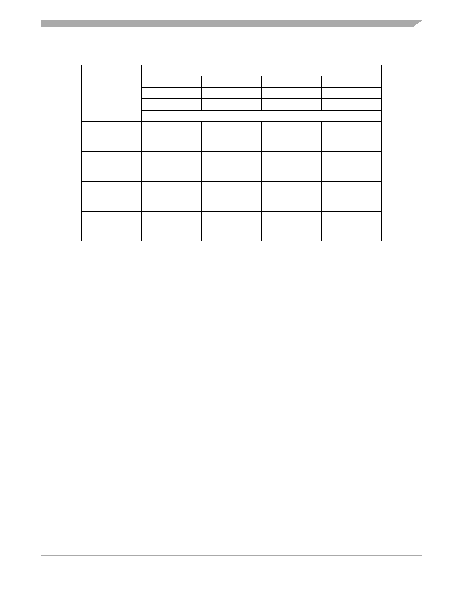
Table 9-1. Timer Summary
XTAL Frequencies
Control Bits
PR1, PR0
4.0 MHz
8.0 MHz
12.0 MHz
Other Rates
1.0 MHz
2.0 MHz
3.0 MHz
(E)
1000 ns
500 ns
333 ns
(1/E)
Main Timer Count Rates
0 0
1 count —
overflow —
1000 ns
65.536 ms
500 ns
32.768 ms
333 ns
21.845 ms
(E/1)
(E/216)
0 1
1 count —
overflow —
4.0
s
262.14 ms
2.0
s
131.07 ms
1.333
s
87.381 ms
(E/4)
(E/218)
1 0
1 count —
overflow —
8.0
s
524.29 ms
4.0
s
262.14 ms
2.667
s
174.76 ms
(E/8)
(E/219)
1 1
1 count —
overflow —
16.0
s
1.049 s
8.0
s
524.29 ms
5.333
s
349.52 ms
(E/16)
(E/220)
相关PDF资料 |
PDF描述 |
|---|---|
| MC68HC11E9BCB3 | 8-BIT, MROM, 3 MHz, MICROCONTROLLER, PDIP56 |
| MC68HC711E20CFU2 | 8-BIT, OTPROM, 2 MHz, MICROCONTROLLER, PQFP64 |
| MC68S711E9CFN2 | 8-BIT, OTPROM, 2 MHz, MICROCONTROLLER, PQCC52 |
| MC68HC11E9MPB2 | 8-BIT, MROM, 2 MHz, MICROCONTROLLER, PQFP52 |
| MC68HC711E9CFS2 | 8-BIT, UVPROM, 2 MHz, MICROCONTROLLER, CQCC52 |
相关代理商/技术参数 |
参数描述 |
|---|---|
| MC68HC11E20VFU2 | 制造商:MOTOROLA 制造商全称:Motorola, Inc 功能描述:Microcontrollers |
| MC68HC11E9 | 制造商:FREESCALE 制造商全称:Freescale Semiconductor, Inc 功能描述:M68HC11E Series Programming Reference Guide |
| MC68HC11E9B3 | 制造商:MOTOROLA 制造商全称:Motorola, Inc 功能描述:8-channel, 8-bit analog-to-digital (A/D) converter |
| MC68HC11E9BCB2 | 制造商:MOTOROLA 制造商全称:Motorola, Inc 功能描述:Microcontrollers |
| MC68HC11E9BCB3 | 制造商:MOTOROLA 制造商全称:Motorola, Inc 功能描述:8-channel, 8-bit analog-to-digital (A/D) converter |
发布紧急采购,3分钟左右您将得到回复。