- 您现在的位置:买卖IC网 > PDF目录11546 > PIC12F683-E/MD (Microchip Technology)IC PIC MCU FLASH 2KX14 8DFN PDF资料下载
参数资料
| 型号: | PIC12F683-E/MD |
| 厂商: | Microchip Technology |
| 文件页数: | 165/176页 |
| 文件大小: | 0K |
| 描述: | IC PIC MCU FLASH 2KX14 8DFN |
| 产品培训模块: | Asynchronous Stimulus |
| Digi-Key 应用说明: | AN0005 PWM Example with Microchip's CCP Module AN0005 Example Code |
| 标准包装: | 91 |
| 系列: | PIC® 12F |
| 核心处理器: | PIC |
| 芯体尺寸: | 8-位 |
| 速度: | 20MHz |
| 外围设备: | 欠压检测/复位,POR,PWM,WDT |
| 输入/输出数: | 5 |
| 程序存储器容量: | 3.5KB(2K x 14) |
| 程序存储器类型: | 闪存 |
| EEPROM 大小: | 256 x 8 |
| RAM 容量: | 128 x 8 |
| 电压 - 电源 (Vcc/Vdd): | 2 V ~ 5.5 V |
| 数据转换器: | A/D 4x10b |
| 振荡器型: | 内部 |
| 工作温度: | -40°C ~ 125°C |
| 封装/外壳: | 8-VDFN 裸露焊盘 |
| 包装: | 管件 |
| 配用: | AC164326-ND - MODULA SKT PM3 20QFN I3-DB12F683-ND - BOARD DAUGHTER ICEPIC3 |
第1页第2页第3页第4页第5页第6页第7页第8页第9页第10页第11页第12页第13页第14页第15页第16页第17页第18页第19页第20页第21页第22页第23页第24页第25页第26页第27页第28页第29页第30页第31页第32页第33页第34页第35页第36页第37页第38页第39页第40页第41页第42页第43页第44页第45页第46页第47页第48页第49页第50页第51页第52页第53页第54页第55页第56页第57页第58页第59页第60页第61页第62页第63页第64页第65页第66页第67页第68页第69页第70页第71页第72页第73页第74页第75页第76页第77页第78页第79页第80页第81页第82页第83页第84页第85页第86页第87页第88页第89页第90页第91页第92页第93页第94页第95页第96页第97页第98页第99页第100页第101页第102页第103页第104页第105页第106页第107页第108页第109页第110页第111页第112页第113页第114页第115页第116页第117页第118页第119页第120页第121页第122页第123页第124页第125页第126页第127页第128页第129页第130页第131页第132页第133页第134页第135页第136页第137页第138页第139页第140页第141页第142页第143页第144页第145页第146页第147页第148页第149页第150页第151页第152页第153页第154页第155页第156页第157页第158页第159页第160页第161页第162页第163页第164页当前第165页第166页第167页第168页第169页第170页第171页第172页第173页第174页第175页第176页
2007 Microchip Technology Inc.
DS41211D-page 87
PIC12F683
12.3.4
BROWN-OUT RESET (BOR)
The BOREN0 and BOREN1 bits in the Configuration
Word register select one of four BOR modes. Two
modes have been added to allow software or hardware
control of the BOR enable. When BOREN<1:0> = 01,
the SBOREN bit of the PCON register enables/disables
the BOR, allowing it to be controlled in software. By
selecting BOREN<1:0> = 10, the BOR is automatically
disabled in Sleep to conserve power and enabled on
wake-up. In this mode, the SBOREN bit is disabled.
See
for
the
Configuration
Word
definition.
A brown-out occurs when VDD falls below VBOR for
“Electrical Specifications”). The brown-out condition
will reset the device. This will occur regardless of VDD
slew rate. A Brown-out Reset may not occur if VDD falls
below VBOR for less than parameter TBOR.
On any Reset (Power-on, Brown-out Reset, Watchdog
Timer, etc.), the chip will remain in Reset until VDD rises
Power-up Timer will be invoked by the Reset and keep
the chip in Reset an additional 64 ms.
If VDD drops below VBOR while the Power-up Timer is
running, the chip will go back into a Brown-out Reset
and the Power-up Timer will be re-initialized. Once VDD
rises above VBOR, the Power-up Timer will execute a
64 ms Reset.
12.3.5
BOR CALIBRATION
The PIC12F683 stores the BOR calibration values in
fuses located in the Calibration Word register (2008h).
The Calibration Word register is not erased when using
the
specified
bulk
erase
sequence
in
the
“PIC12F6XX/16F6XX Memory Programming Specifi-
cation”
(DS41204)
and
thus,
does
not
require
reprogramming.
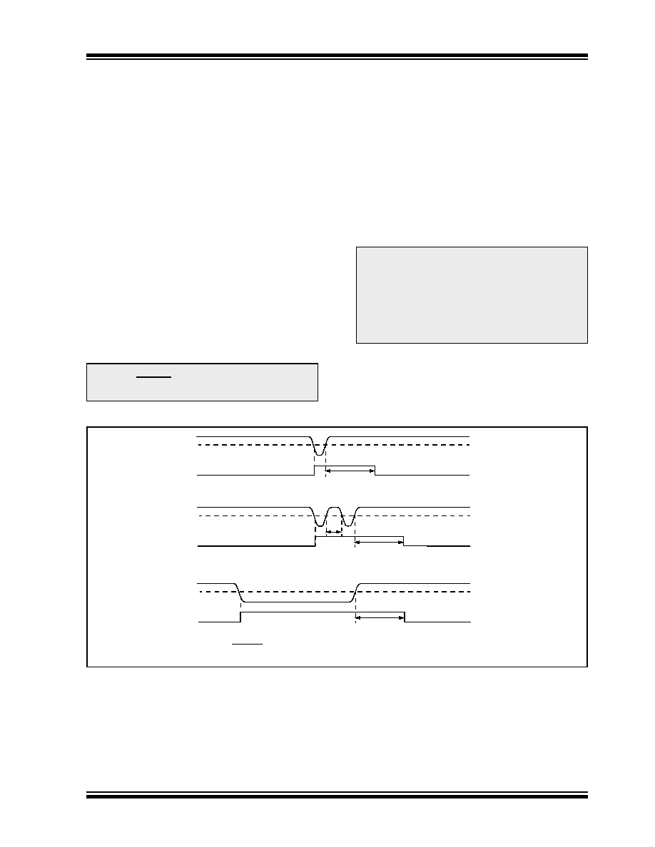
FIGURE 12-3:
BROWN-OUT SITUATIONS
Note:
The Power-up Timer is enabled by the
PWRTE bit in the Configuration Word
register.
Note:
Address 2008h is beyond the user pro-
gram memory space. It belongs to the
special
configuration
memory
space
(2000h-3FFFh), which can be accessed
only
during
programming.
See
“PIC12F6XX/16F6XX Memory Program-
ming Specification” (DS41204) for more
information.
64 ms(1)
VBOR
VDD
Internal
Reset
VBOR
VDD
Internal
Reset
64 ms(1)
< 64 ms
64 ms(1)
VBOR
VDD
Internal
Reset
Note 1:
64 ms delay only if PWRTE bit is programmed to ‘0’.
相关PDF资料 |
PDF描述 |
|---|---|
| PIC18LF43K22T-I/MV | IC MCU 8BIT 8KB FLASH 40UQFN |
| V375C48M75BG | CONVERTER MOD DC/DC 48V 75W |
| V375C48M75BF | CONVERTER MOD DC/DC 48V 75W |
| PIC18F43K22T-I/MV | IC MCU 8BIT 8KB FLASH 40UQFN |
| V375C48M75B3 | CONVERTER MOD DC/DC 48V 75W |
相关代理商/技术参数 |
参数描述 |
|---|---|
| PIC12F683-I/MD | 功能描述:8位微控制器 -MCU 3.5KB 128 RAM 6I/O RoHS:否 制造商:Silicon Labs 核心:8051 处理器系列:C8051F39x 数据总线宽度:8 bit 最大时钟频率:50 MHz 程序存储器大小:16 KB 数据 RAM 大小:1 KB 片上 ADC:Yes 工作电源电压:1.8 V to 3.6 V 工作温度范围:- 40 C to + 105 C 封装 / 箱体:QFN-20 安装风格:SMD/SMT |
| PIC12F683-I/MDQTP | 制造商:MICROCHIP 制造商全称:Microchip Technology 功能描述:8-Pin Flash-Based, 8-Bit CMOS Microcontrollers with nanoWatt Technology |
| PIC12F683-I/MF | 功能描述:8位微控制器 -MCU 3.5KB 128 RAM 6 I/O RoHS:否 制造商:Silicon Labs 核心:8051 处理器系列:C8051F39x 数据总线宽度:8 bit 最大时钟频率:50 MHz 程序存储器大小:16 KB 数据 RAM 大小:1 KB 片上 ADC:Yes 工作电源电压:1.8 V to 3.6 V 工作温度范围:- 40 C to + 105 C 封装 / 箱体:QFN-20 安装风格:SMD/SMT |
| PIC12F683-I/MF | 制造商:Microchip Technology Inc 功能描述:8BIT FLASH MCU SMD 12F683 DFN-8 |
| PIC12F683-I/MFQTP | 制造商:MICROCHIP 制造商全称:Microchip Technology 功能描述:8-Pin Flash-Based, 8-Bit CMOS Microcontrollers with nanoWatt Technology |
发布紧急采购,3分钟左右您将得到回复。