- 您现在的位置:买卖IC网 > PDF目录11815 > SC28C94A1N,112 (NXP Semiconductors)IC UART QUAD W/FIFO 48-DIP PDF资料下载
参数资料
| 型号: | SC28C94A1N,112 |
| 厂商: | NXP Semiconductors |
| 文件页数: | 29/39页 |
| 文件大小: | 0K |
| 描述: | IC UART QUAD W/FIFO 48-DIP |
| 标准包装: | 7 |
| 特点: | 故障启动位检测 |
| 通道数: | 4,QUART |
| FIFO's: | 8 字节 |
| 电源电压: | 5V |
| 带自动流量控制功能: | 是 |
| 带故障启动位检测功能: | 是 |
| 带调制解调器控制功能: | 是 |
| 带CMOS: | 是 |
| 安装类型: | 通孔 |
| 封装/外壳: | 48-DIP(0.600",15.24mm) |
| 供应商设备封装: | 48-DIP |
| 包装: | 管件 |
| 其它名称: | 568-1115-5 935262535112 SC28C94A1N |
第1页第2页第3页第4页第5页第6页第7页第8页第9页第10页第11页第12页第13页第14页第15页第16页第17页第18页第19页第20页第21页第22页第23页第24页第25页第26页第27页第28页当前第29页第30页第31页第32页第33页第34页第35页第36页第37页第38页第39页
Philips Semiconductors
Product data sheet
SC28C94
Quad universal asynchronous receiver/transmitter (QUART)
2006 Aug 09
35
through the most significant 6 bits. The result of this is that the
channel value does not ’bid’. However the logic is such that other
parts of the bid being equal the condition of the highest channel will
be captured in CIR. The increasing order of the channels is A, B, C,
D. Thus channel D is the ”strongest” of the four.
It could be that the giving the highest strength to channel D may,
from time to time, not be what would be most desired. Further it
may be desired to alter the authority of a channel’s bid. This may
be done by setting the Rx and/or Tx interrupt bits in MR0 and MR1
to values different than zero. This will have the effect of not allowing
the associated receiver or transmitter to bid until its FIFO reaches a
particular fill level. Although this compromises the idea of the
bidding interrupt scheme, it is entirely safe to use. In fact it is setting
of MR0 and MR1 interrupt bits to zero that causes the receiver to
stop bidding when it is empty and causes the transmitter to stop
bidding when it is full. Altering the MR0 and MR1 interrupt bits only
changes the level at which the Rx & Tx bidding is stopped.
See the “Interrupt Note on 28C94” which refers to the use of the MR
registers in controlling the Rx and Tx bidding.
In normal operation the character of an interrupt will be controlled by
the above registers in conjunction with the IMR (Interrupt Mask
Register (one for each DUART)) . The function of the IMR will be to
enable bidding of any particular source. Recall that the QUART has
18 functions which may generate an interrupt.
The format of the interrupt vector is controlled by the ICR[1:0] bits.
The formats are shown in Table 10. The purpose of the vector
modification is to allow the interrupting source (either channel or
type and channel) to direct the processor to appropriate service
routine. We have found that some users wish to use extremely tight
loops for the service routines and find the addition of several tests of
status bytes to be very ’expensive’ in processor time.
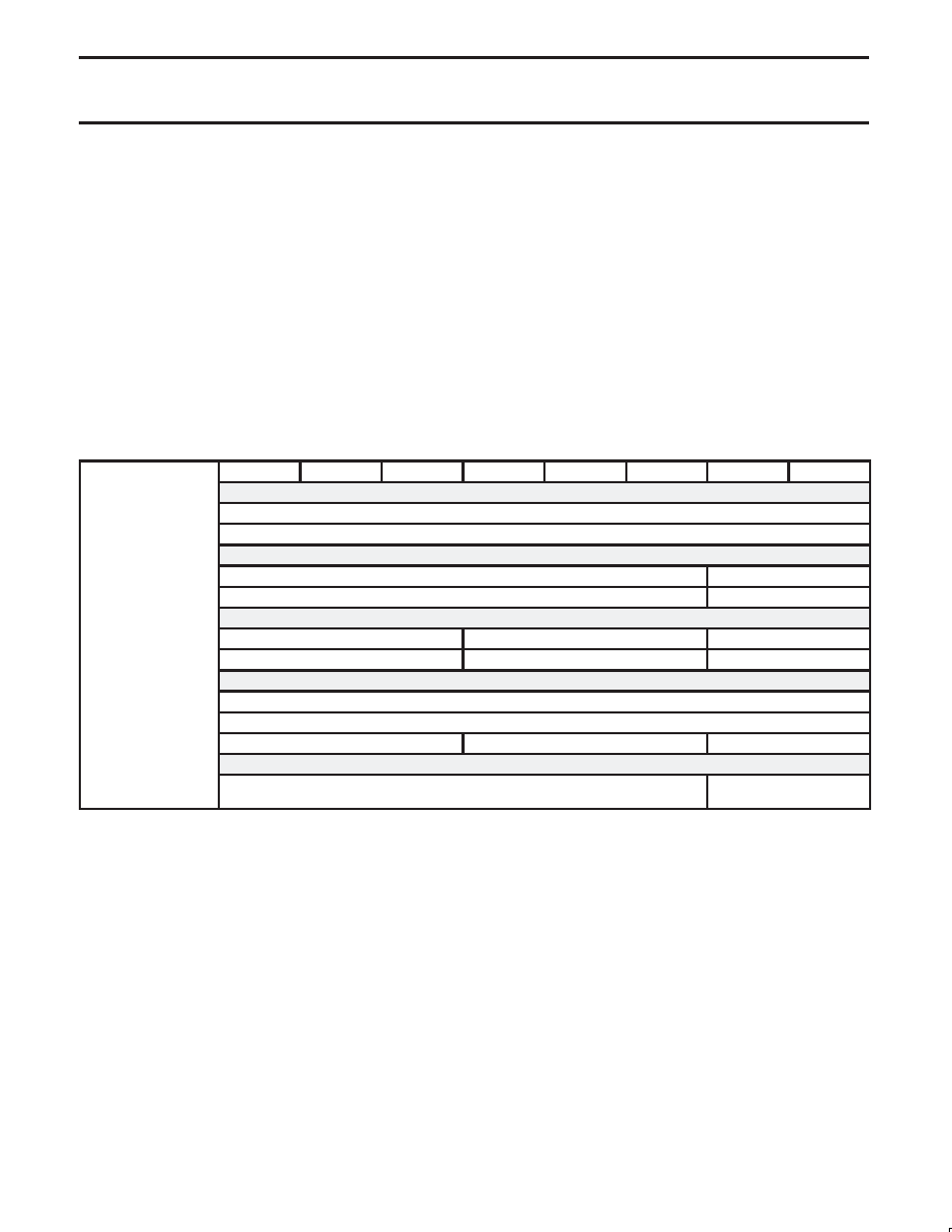
Table 10.
Configuration of Interrupt Vector for the QUART
BIT 7
BIT 6
BIT 5
BIT 4
BIT 3
BIT 2
BIT 1
BIT 0
Interrupt vector for
→
ICR[1 0] 00
INTERRUPT VECTOR FORMATS (Controlled by ICR[1:0])
ICR[1:0]=00
IVR[7:0]
Full interrupt vector
Interrupt vector for
→
ICR[1 0] 01
ICR[1:0]=01
IVR[7:2]
ICR[1:0]
Interrupt vector 6 MSBs
Channel number
Interrupt vector for
→
ICR[1 0] 10
ICR[1:0]=10
IVR[7:5]
ICR[4:2]
ICR[1:0]
Interrupt vector 3 MSBs
Interrupt type
Channel number
Interrupt vector for
→
ICR[1 0] 11 (I hibit)
ICR[1:0]=11 (Inhibit)
Inhibit vector output. (Set bus to FFh)
CURRENT INTERRUPT REGISTER FORMAT CIR[7:0]
Rx or Tx byte count
Interrupt type: R/Tx CT COS BRK
Channel number
INTERRUPT CONTROL REGISTER FORMAT ICR[0:7]
Interrupt threshold ICR[7:2]
Interrupt vector format
ICR[1:0]
NOTE ON QUART INTERFACE TO ITS
CONTROLLING PROCESSOR
The QUART, has been designed to interface in either the
synchronous interrupt environment (without DACKN) or the
asynchronous interrupt environment (with DACKN). The 80xxx
devices of Intel design are usually operated in a synchronous
interrupt mode while those of Motorola design, 68xxx devices,
operate in an asynchronous interrupt mode.
Note: Synchronous and asynchronous interrupt modes are not
in any way associated with synchronous or asynchronous data
transmission.
The QUART has been designed with the pins required to service
either interface. In general then it is probable that in any application
some of the interface pins will not be used. This note discusses
what is required for the ”text book” connections of the two methods.
It should be noted that features of either method are not mutually
exclusive.
The interface pins are all active low. (at VSS or ground) The pins
used for normal reading and writing to the QUART (the generation of
a bus cycle) are CEN (Chip Enable), RDN (Read Enable), WRN
(Write Enable). The pins used in the interrupt service are IRQN
(Interrupt Request), IACKN (Interrupt Acknowledge). The pin used
for data transfer is DACKN (Data Acknowledge). IRQN and DACKN
are open drain outputs.
DACKN signaling can be enabled or disabled via writing to address
27h or 26h respectively. Note that if DACKN is enabled that writing
to the QUART will occur on the falling edge of DACKN. The use of
hardware reset (required at power up) enables DACKN.
The Asynchronous Interface
Those familiar with 68xxx I/O will note the use of the two pins RDN
and WRN to be in conflict with 68xxx devices use of the one R/WN
pin. The R/WN must be inverted such that the R/WN may drive the
WRN input while the inversion of R/WN drives the RDN input. It is
good practice to condition the inversion of R/WN such that RDN will
not become active on the termination of a write to the QUART while
CEN is still asserted. These short periods of read could upset FIFO
pointers in the chip.
During a read of the QUART DACKN signals that valid data is on the
data bus. During a write to the QUART DACKN signals that data
placed on the bus by the control processor has been written to the
相关PDF资料 |
PDF描述 |
|---|---|
| V24C24H150B | CONVERTER MOD DC/DC 24V 150W |
| SC16C554DIA68,512 | IC UART QUAD W/FIFO 68-PLCC |
| AT32UC3L064-D3HR | MCU AVR32 64K FLASH 48TTLGA |
| ST16C550CP40 | IC UART FIFO 16BYTE 40PDIP |
| V24B24H150BG3 | CONVERTER MOD DC/DC 24V 150W |
相关代理商/技术参数 |
参数描述 |
|---|---|
| SC28L194 | 制造商:PHILIPS 制造商全称:NXP Semiconductors 功能描述:Quad UART for 3.3V and 5V supply voltage |
| SC28L194A1A | 功能描述:UART 接口集成电路 3V-5V 4CH UART INTEL/MOT INTRF RoHS:否 制造商:Texas Instruments 通道数量:2 数据速率:3 Mbps 电源电压-最大:3.6 V 电源电压-最小:2.7 V 电源电流:20 mA 最大工作温度:+ 85 C 最小工作温度:- 40 C 封装 / 箱体:LQFP-48 封装:Reel |
| SC28L194A1A,512 | 功能描述:UART 接口集成电路 3V-5V 4CH UART RoHS:否 制造商:Texas Instruments 通道数量:2 数据速率:3 Mbps 电源电压-最大:3.6 V 电源电压-最小:2.7 V 电源电流:20 mA 最大工作温度:+ 85 C 最小工作温度:- 40 C 封装 / 箱体:LQFP-48 封装:Reel |
| SC28L194A1A,518 | 功能描述:UART 接口集成电路 3V-5V 4CH UART RoHS:否 制造商:Texas Instruments 通道数量:2 数据速率:3 Mbps 电源电压-最大:3.6 V 电源电压-最小:2.7 V 电源电流:20 mA 最大工作温度:+ 85 C 最小工作温度:- 40 C 封装 / 箱体:LQFP-48 封装:Reel |
| SC28L194A1A,529 | 功能描述:UART 接口集成电路 3V-5V 4CH UART RoHS:否 制造商:Texas Instruments 通道数量:2 数据速率:3 Mbps 电源电压-最大:3.6 V 电源电压-最小:2.7 V 电源电流:20 mA 最大工作温度:+ 85 C 最小工作温度:- 40 C 封装 / 箱体:LQFP-48 封装:Reel |
发布紧急采购,3分钟左右您将得到回复。