- 您现在的位置:买卖IC网 > PDF目录10908 > SI3015-F-FS (Silicon Laboratories Inc)IC ISOMODEM LINE-SIDE DAA 16SOIC PDF资料下载
参数资料
| 型号: | SI3015-F-FS |
| 厂商: | Silicon Laboratories Inc |
| 文件页数: | 26/94页 |
| 文件大小: | 0K |
| 描述: | IC ISOMODEM LINE-SIDE DAA 16SOIC |
| 标准包装: | 48 |
| 系列: | ISOmodem® |
| 数据格式: | V.90 |
| 波特率: | 2.4k |
| 电源电压: | 3.3V,5V |
| 安装类型: | 表面贴装 |
| 封装/外壳: | 16-SOIC(0.154",3.90mm 宽) |
| 供应商设备封装: | 16-SOIC N |
| 包装: | 管件 |
第1页第2页第3页第4页第5页第6页第7页第8页第9页第10页第11页第12页第13页第14页第15页第16页第17页第18页第19页第20页第21页第22页第23页第24页第25页当前第26页第27页第28页第29页第30页第31页第32页第33页第34页第35页第36页第37页第38页第39页第40页第41页第42页第43页第44页第45页第46页第47页第48页第49页第50页第51页第52页第53页第54页第55页第56页第57页第58页第59页第60页第61页第62页第63页第64页第65页第66页第67页第68页第69页第70页第71页第72页第73页第74页第75页第76页第77页第78页第79页第80页第81页第82页第83页第84页第85页第86页第87页第88页第89页第90页第91页第92页第93页第94页
Si2400
32
Rev. 1.3
must be disabled by setting S14[7] (MRCD) = 1b when
using this command to ensure the host does not
confuse a result code with data. w## and r# are not
required to be on separate lines (no <CR> between
them). Once a <CR> is encountered, AT is required to
begin the next AT command. For example, write the
value 58h to S34 and read it back using # commands
and ATSR commands.
The economy of the # commands is clearly evident from
this example. One caveat when using the # commands
is that the ASCII equivalents of the response can be
displayed as special or graphic characters when using a
terminal emulator program such as HyperTerminal.
However, in an embedded system, it is easy to send
non-ASCII characters.
6.4.5. m# Command Monitor S-Register
This command is similar to the r# command but is
repeated at the DTE rate until a new byte is transmitted
to the modem. The modem will echo the register
contents to the display as the ASCII equivalent of the
hexadecimal value of the contents. This command
executes immediately and does not require a carriage
return. Modem result codes must be disabled by setting
S14[7] (MRCD) = 1b when using this command to
ensure that the host does not confuse a result code with
data.
6.4.6. q# Command Read S-Register with 0x5500
Offset
This command is the same as the r# command except
that the response from the Si2400 is formatted as the
hexadecimal value 0x55aa where aa is the hexadecimal
value of the S-register contents. From a terminal, the #
following q is the ASCII equivalent of the hexadecimal
address of the S-register. This command executes
immediately and does not require a carriage return. The
0x5500 offset in the value of the register contents
prevents confusion between data and result codes and
permits the result codes to remain enabled.
Z
Software Reset (upper-case Z)
The “Z” command causes a software reset to occur in
the device whereby the registers will return to their
default power up value with the exception of E0, E2,
E4–E7, F8, and F9. These registers are not reset, so
the Si2400 will maintain its current DTE settings, GPIO
definitions, tone detect and transmit settings, and
overload and billing tone detection status. The hardware
reset pin, RESET (Si2400, pin 8), is used to reset the
Si2400 to factory default settings. If other commands
follow on the same line, another AT is needed after the
“Z” (e.g., ATZATS07=06<CR>).
z
Wakeup on Ring (lower-case z)
The Si2400 enters a low-power mode wherein the DSP
and microcontroller are powered down. The serial
interface also stops functioning. In this mode, only the
line-side chip (Si3015) and the communication link
function. An incoming ring signal or line transient
causes the Si2400 to power up and echo an “R”.
Without a ring signal, the host must perform a hardware
reset (Si2400, pin 8) to power up the Si2400. Return
from wake-on-ring can also be set to trigger the ALERT
pin by setting S62[4] (WOR) = 1b.
6.5. Alarm Industry AT Commands
The Si2400 supports a complete set of commands
necessary for making connections in security industry
systems. The Si2400 is configurable in three modes for
these applications. The first mode, DTMF send and
receive, is selected with the “!1” command. The second
mode uses FSK transmit with a tone acknowledgement
and is selected with “!2”. Finally, “!7” is selected for the
tone-on/tone-off mode.
The following are a few general comments about the
use of “!” commands. Specific details for each command
is given below. The first instance of the “!” must be on
the same line as the ATDT or ATDP command. DRT
must be set to data mode (SE4[5:4] (DRT) = 0b) before
attempting to send tones after a “!” command. The three
data-mode escape sequences (“+++”, “escape” pin and
“ninth-bit”) only function in “!2” mode. However, using
the “+++” or “ninth-bit” is not recommended because
characters could be sent to and misinterpreted by the
remote modem. Only the “escape pin” (Si2400, pin 14)
is recommended for use in the “!2” mode. The “!1” and
“!7” modes have special escape provisions described in
their respective sections below. The AT commands for
Alarm Industry applications are described in Table 18.
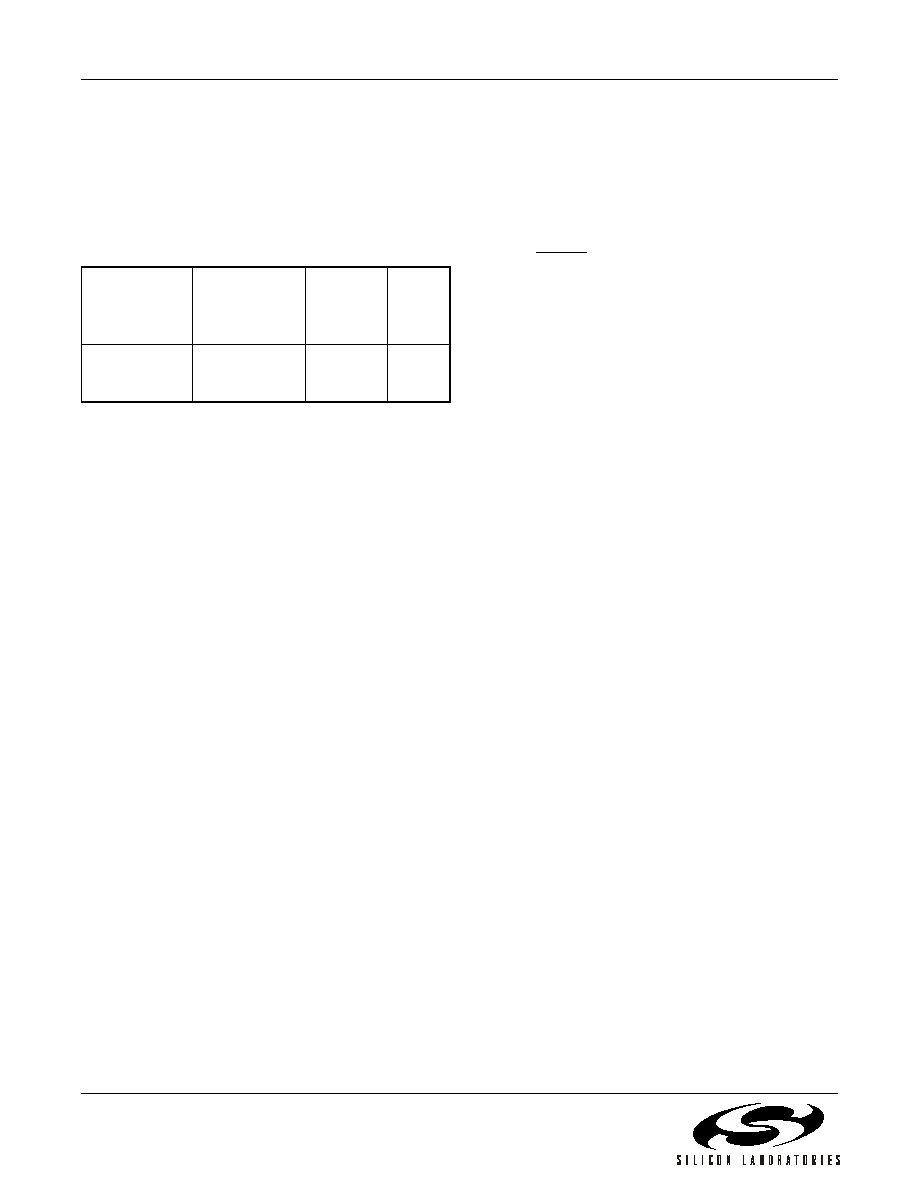
Terminal
Entry
Sent to
Modem (hex)
Response
(hex)
Display
ATw4Xr4
41 54 77 34 58
72 34
58
X
ATS34=58S34
?<CR>
41 54 53 33 34
3D 35 38 53 33
34 3F 0D
35 38
58
相关PDF资料 |
PDF描述 |
|---|---|
| SI3050-E1-FM | IC VOICE DAA SYSTEM SIDE 24QFN |
| JBXEA2G07FSSDS | CONN RCPT 7POS DOUBLE NUT SOLDER |
| VE-J6V-IY-B1 | CONVERTER MOD DC/DC 5.8V 50W |
| VE-J6T-IY-B1 | CONVERTER MOD DC/DC 6.5V 50W |
| VE-2NX-IX-F1 | CONVERTER MOD DC/DC 5.2V 75W |
相关代理商/技术参数 |
参数描述 |
|---|---|
| SI3015-F-FSR | 制造商:Silicon Laboratories Inc 功能描述:Modem Chip Chipset 2.4Kbps 16-Pin SOIC T/R 制造商:Silicon Laboratories Inc 功能描述:MODEM CHIP CHIPSET ISOMODEM 2.4KBPS 16SOIC - Tape and Reel 制造商:Silicon Laboratories 功能描述:Modem Chip Chipset 2.4Kbps 16-Pin SOIC T/R |
| SI3015-FS | 功能描述:IC ISOMODEM LINE-SIDE DAA 16SOIC RoHS:是 类别:集成电路 (IC) >> 接口 - 调制解调器 - IC 和模块 系列:ISOmodem® 标准包装:25 系列:- 数据格式:V.21,V.22,V.23,V.29,V.32,V.34,V.90,V.92,Bell 103,Bell 212A 波特率:33.6k 电源电压:3.3V 安装类型:- 封装/外壳:- 供应商设备封装:- 包装:托盘 配用:591-1013-ND - KIT DEV SOCKETMODEM PARALLEL591-1009-ND - KIT DEV SRL SOCKETMODEM UNIVERSL 其它名称:MT5656SMI-P-V-34.R2-SPMT5656SMI-P-V-34.R2-SP-NDQ4711574 |
| SI3015-FSR | 制造商:Silicon Laboratories Inc 功能描述:SI2403 ISOMODEM LINE-SIDE LEAD-FREE SOIC 0 TO 70 DEG. C - Tape and Reel |
| SI3015-KS | 功能描述:电信线路管理 IC SI2400 Line Side RoHS:否 制造商:STMicroelectronics 产品:PHY 接口类型:UART 电源电压-最大:18 V 电源电压-最小:8 V 电源电流:30 mA 最大工作温度:+ 85 C 最小工作温度:- 40 C 安装风格:SMD/SMT 封装 / 箱体:VFQFPN-48 封装:Tray |
| SI3015-KSR | 功能描述:电信线路管理 IC SI2400 Line Side RoHS:否 制造商:STMicroelectronics 产品:PHY 接口类型:UART 电源电压-最大:18 V 电源电压-最小:8 V 电源电流:30 mA 最大工作温度:+ 85 C 最小工作温度:- 40 C 安装风格:SMD/SMT 封装 / 箱体:VFQFPN-48 封装:Tray |
发布紧急采购,3分钟左右您将得到回复。