- 您现在的位置:买卖IC网 > PDF目录69348 > ST5451D (STMICROELECTRONICS) 1 CHANNEL(S), SERIAL COMM CONTROLLER, PDSO28 PDF资料下载
参数资料
| 型号: | ST5451D |
| 厂商: | STMICROELECTRONICS |
| 元件分类: | 微控制器/微处理器 |
| 英文描述: | 1 CHANNEL(S), SERIAL COMM CONTROLLER, PDSO28 |
| 封装: | SO-28 |
| 文件页数: | 2/34页 |
| 文件大小: | 269K |
| 代理商: | ST5451D |
第1页当前第2页第3页第4页第5页第6页第7页第8页第9页第10页第11页第12页第13页第14页第15页第16页第17页第18页第19页第20页第21页第22页第23页第24页第25页第26页第27页第28页第29页第30页第31页第32页第33页第34页
MONR2
Monitor Receive Register 2
After reset FFH
(GCI and TE mode only)
The value read from MONR2 gives the
value of the byte received from M
channel in 2nd GCI channel.
TSR
Time Slot Register
After reset 00
TSR7 TSR6 TSR5 TSR4 TSR3 TSR2 TSR1 TSR0
In GCI mode (MDS1= 1 in CF Register)
a) CCS=1 in CF Reg. (64 Kbit/s)
Then: TSR2 indicates B1 or B2
TSR4/7 indicate position of
GCI channel
b) CCS=0 in CF Reg. (16 Kbit/s)
Then: TSR4/7 indicate position of
GCI and its D channel
In Multiplexed Mode
(MDS1=0 in CF Register)
a) CCS=1 in CF Reg. (64 Kbit/s)
Then: TSR2/7 indicate channel
position in the 64 time slots
multiplex
b) CCS=0 in CF Reg. (16 Kbit/s)
Then: TSR0/7 indicate channel
position in the 256 time slots
multiplex.
CA
Configurationn Register A
After reset 00
CA7
CA6
CA5
CA4
CA3
CA2
CA1
CA0
SAPI 0 is recognized
CA0 = 1
CA1
SAPI 63
CA1 = 1
CA2
SAPI x
CA2 = 1
CA3
SAPI y
CA3 = 1
CA4
TEI 127
CA4 = 1
CA5
TEI z
CA5 = 1
CA6
TEI t
CA6 = 1
CA7
Address filter active
CA7 = 1
CB
Configuration register B
After reset 00
Content of CB indicate SAPI x value
High Order 6 Bits
SAPI
0
CC
Configuration Register C
After reset 00
Content of CC indicate SAPI y value
High Order 6 Bits
SAPI
0
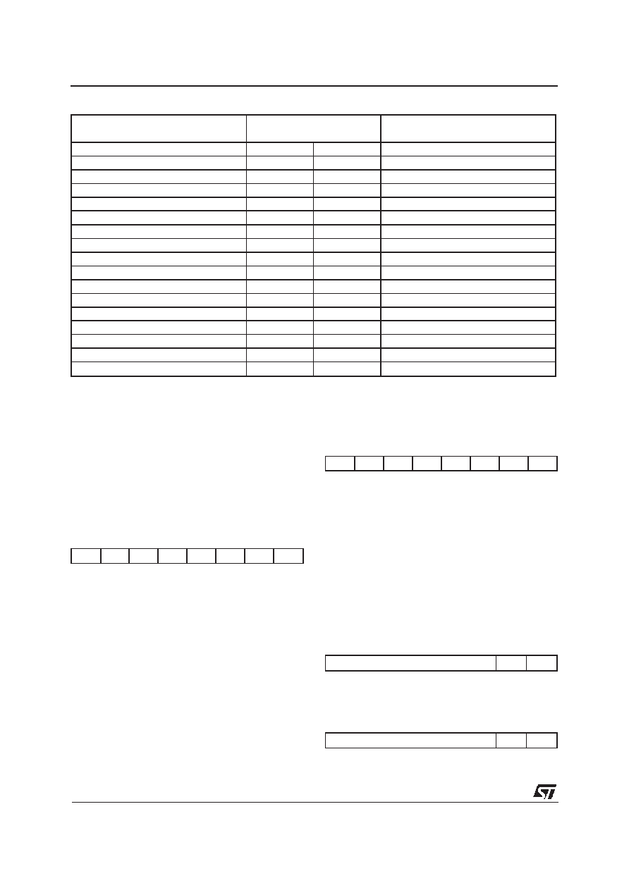
N (number of bytes in the
frame received without CRC)
Counter
n (number of 32 bytes blocks
received )
765
432 1 0
Nn
m
n
1 Min
000
00001
0
2
000
00010
0
3
000
00011
0
30
000
11110
0
31
000
11111
0
32
001
00000
1
33
001
00001
1
62
001
11110
1
63
001
11111
1
64
010
00000
2
222
110
11110
6
223
110
11111
6
224
111
11111
7
256
111
00000
7
257
111
00001
7
-
111
-
7
TABLE 3
ST5451
10/34
相关PDF资料 |
PDF描述 |
|---|---|
| ST6200CN1/XXX | 8-BIT, MROM, 8 MHz, MICROCONTROLLER, PDSO16 |
| ST6203CB3/XXX | 8-BIT, MROM, 8 MHz, MICROCONTROLLER, PDIP16 |
| ST6201CN6/XXX | 8-BIT, MROM, 8 MHz, MICROCONTROLLER, PDSO16 |
| ST6201CM3/XXX | 8-BIT, MROM, 8 MHz, MICROCONTROLLER, PDSO16 |
| ST6201CM6/XXX | 8-BIT, MROM, 8 MHz, MICROCONTROLLER, PDSO16 |
相关代理商/技术参数 |
参数描述 |
|---|---|
| ST5451L | 制造商:Valor 功能描述: |
| ST5451N | 制造商:未知厂家 制造商全称:未知厂家 功能描述:ISDN, Other/Special/Miscellaneous |
| ST5452L | 制造商:Pulse 功能描述:- Bulk |
| ST5453L | 制造商:Pulse 功能描述:- Bulk |
| ST5454L | 制造商:Pulse 功能描述:- Bulk |
发布紧急采购,3分钟左右您将得到回复。