- 您现在的位置:买卖IC网 > PDF目录98145 > ST72T774S9T1 (STMICROELECTRONICS) 8-BIT, OTPROM, 8 MHz, MICROCONTROLLER, PQFP44 PDF资料下载
参数资料
| 型号: | ST72T774S9T1 |
| 厂商: | STMICROELECTRONICS |
| 元件分类: | 微控制器/微处理器 |
| 英文描述: | 8-BIT, OTPROM, 8 MHz, MICROCONTROLLER, PQFP44 |
| 封装: | TQFP-44 |
| 文件页数: | 120/144页 |
| 文件大小: | 1280K |
| 代理商: | ST72T774S9T1 |
第1页第2页第3页第4页第5页第6页第7页第8页第9页第10页第11页第12页第13页第14页第15页第16页第17页第18页第19页第20页第21页第22页第23页第24页第25页第26页第27页第28页第29页第30页第31页第32页第33页第34页第35页第36页第37页第38页第39页第40页第41页第42页第43页第44页第45页第46页第47页第48页第49页第50页第51页第52页第53页第54页第55页第56页第57页第58页第59页第60页第61页第62页第63页第64页第65页第66页第67页第68页第69页第70页第71页第72页第73页第74页第75页第76页第77页第78页第79页第80页第81页第82页第83页第84页第85页第86页第87页第88页第89页第90页第91页第92页第93页第94页第95页第96页第97页第98页第99页第100页第101页第102页第103页第104页第105页第106页第107页第108页第109页第110页第111页第112页第113页第114页第115页第116页第117页第118页第119页当前第120页第121页第122页第123页第124页第125页第126页第127页第128页第129页第130页第131页第132页第133页第134页第135页第136页第137页第138页第139页第140页第141页第142页第143页第144页
ST72774/ST727754/ST72734
77/144
TIMING MEASUREMENT UNIT (Cont’d)
4.5.4 Register Description
CONTROL STATUS REGISTER (TMUCSR)
Bit 7:2 - Read only
Bit 1:0 - Read/Write
Reset Value: 1111 1100 (FCh)
Bit 7:5 = T2[10:8]
MSB of T2 Counter.
Most Significant Bits of the T2 counter value (see
T2 Counter register description).
Bit 4:2= T1[10:8]
MSB T1 Counter.
Most Significant Bits of the T1 counter value (see
T1 Counter register description).
Bit 1 = H_V
Horizontal or Vertical Measurement.
This bit is set and cleared by software to select the
type of measurement. It cannot be modified while
the START bit = 1 (measurement in progress).
0: Vertical measurement.
1: Horizontal measurement.
Bit 0 = START
Start measurement.
This bit is set by software and cleared by hardware
when the measurements are completed. It can not
be cleared by software.
0: Measurement done.
1: Start measurement.
T1 COUNTER REGISTER (TMUT1CR)
Read Only
Reset Value: 1111 1111 (FFh)
This is an 8-bit register that contains the low part of
the counter value.
When a T1 measurement is finished (rising edge
on AV input), the 11-bit counter value is transferred
to this register and to the T1[10:8] bits in the CSR
register.
T1 is H1 value if the H_V bit = 1.
T1 is V1 value if the H_V bit = 0.
T2 COUNTER REGISTER (TMUT2CR)
Read Only
Reset Value: 1111 1111(FFh)
This is an 8-bit register that contains the low part of
the counter value.
When a T2 measurement is finished (rising edge
on the selected sync signal), the 11-bit counter
value is transferred to this register and to the
T2[10:8] bits in the CSR register.
T2 is H2 value if the H_V bit = 1.
T2 is V2 value if the H_V bit = 0.
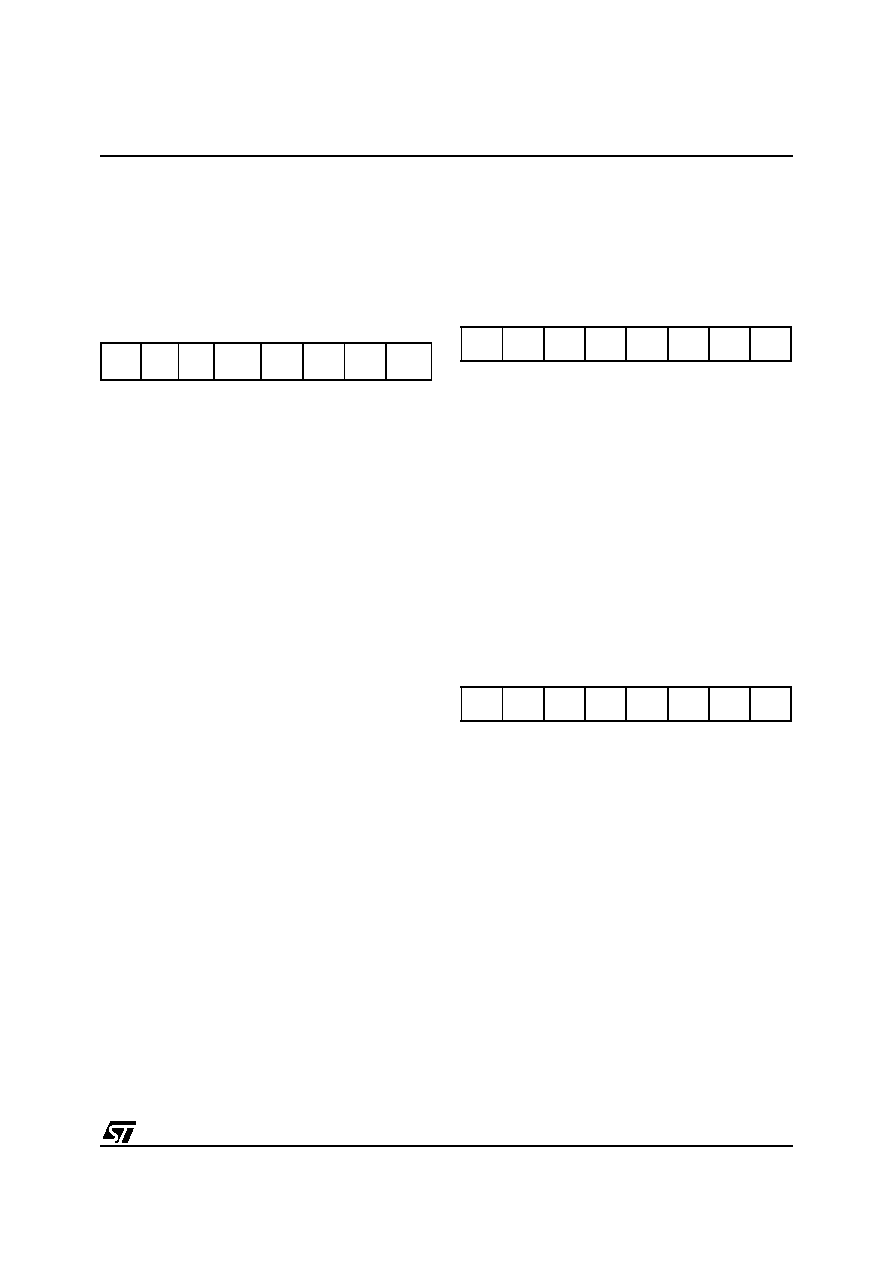
70
T2[10] T2[9] T2[8] T1[10] T1[9] T1[8]
H_V START
70
T1[7]
T1[0]
70
T2[7]
T2[0]
相关PDF资料 |
PDF描述 |
|---|---|
| ST7294C6B6 | 8-BIT, MROM, 4 MHz, MICROCONTROLLER, PDIP28 |
| ST72T94C6M6 | 8-BIT, OTPROM, MICROCONTROLLER, PDSO28 |
| ST72C171K2B6 | 8-BIT, FLASH, 8 MHz, MICROCONTROLLER, PDIP32 |
| ST72E85A5G0 | 8-BIT, UVPROM, 4.332 MHz, MICROCONTROLLER, CQFP80 |
| ST72F321J9T7 | 8-BIT, FLASH, 8 MHz, MICROCONTROLLER, PQFP44 |
相关代理商/技术参数 |
参数描述 |
|---|---|
| ST730 | 制造商:IRF 制造商全称:International Rectifier 功能描述:PHASE CONTROL THYRISTORS Hockey Puk Version |
| ST7-30 | 制造商:SUPERWORLD 制造商全称:Superworld Electronics 功能描述:POWER TRANSFORMER |
| ST-7300 | 制造商:GC Electronics 功能描述: |
| ST730186-3 | 制造商:KEMET Corporation 功能描述: 制造商:KET 功能描述: |
| ST730268-1 | 制造商:KEMET Corporation 功能描述: 制造商:KET 功能描述: |
发布紧急采购,3分钟左右您将得到回复。