- 您现在的位置:买卖IC网 > PDF目录98145 > ST72T774S9T1 (STMICROELECTRONICS) 8-BIT, OTPROM, 8 MHz, MICROCONTROLLER, PQFP44 PDF资料下载
参数资料
| 型号: | ST72T774S9T1 |
| 厂商: | STMICROELECTRONICS |
| 元件分类: | 微控制器/微处理器 |
| 英文描述: | 8-BIT, OTPROM, 8 MHz, MICROCONTROLLER, PQFP44 |
| 封装: | TQFP-44 |
| 文件页数: | 131/144页 |
| 文件大小: | 1280K |
| 代理商: | ST72T774S9T1 |
第1页第2页第3页第4页第5页第6页第7页第8页第9页第10页第11页第12页第13页第14页第15页第16页第17页第18页第19页第20页第21页第22页第23页第24页第25页第26页第27页第28页第29页第30页第31页第32页第33页第34页第35页第36页第37页第38页第39页第40页第41页第42页第43页第44页第45页第46页第47页第48页第49页第50页第51页第52页第53页第54页第55页第56页第57页第58页第59页第60页第61页第62页第63页第64页第65页第66页第67页第68页第69页第70页第71页第72页第73页第74页第75页第76页第77页第78页第79页第80页第81页第82页第83页第84页第85页第86页第87页第88页第89页第90页第91页第92页第93页第94页第95页第96页第97页第98页第99页第100页第101页第102页第103页第104页第105页第106页第107页第108页第109页第110页第111页第112页第113页第114页第115页第116页第117页第118页第119页第120页第121页第122页第123页第124页第125页第126页第127页第128页第129页第130页当前第131页第132页第133页第134页第135页第136页第137页第138页第139页第140页第141页第142页第143页第144页
ST72774/ST727754/ST72734
87/144
4.7 IC SINGLE MASTER BUS INTERFACE (I2C)
4.7.1 Introduction
The I2C Bus Interface serves as an interface
between the microcontroller and the serial I2C bus.
It provides single master functions, and controls all
I2C bus-specific sequencing, protocol and timing.
It supports fast IC mode (400kHz).
4.7.2 Main Features
– Parallel bus /I2C protocol converter
– Interrupt generation
– Standard I2C mode /Fast I2C mode
– 7-bit Addressing
s
I2C single Master Mode
– End of byte transmission flag
– Transmitter/Receiver flag
– Clock generation
4.7.3 General Description
In addition to receiving and transmitting data, this
interface converts it from serial to parallel format
and vice versa, using either an interrupt or polled
handshake. The interrupts are enabled or disabled
by software. The interface is connected to the I2C
bus by a data pin (SDAI) and by a clock pin (SCLI).
It can be connected both with a standard I2C bus
and a Fast I2C bus. This selection is made by
software.
Mode Selection
The interface can operate in the two following
modes:
– Master transmitter/receiver
By default, it is idle.
The interface automatically switches from idle to
master after it generates a START condition and
from master to idle after it generates a STOP
condition.
Communication Flow
The
interface
initiates
a
data
transfer
and
generates the clock signal. A serial data transfer
always begins with a start condition and ends with
a stop condition. Both start and stop conditions are
generated by software.
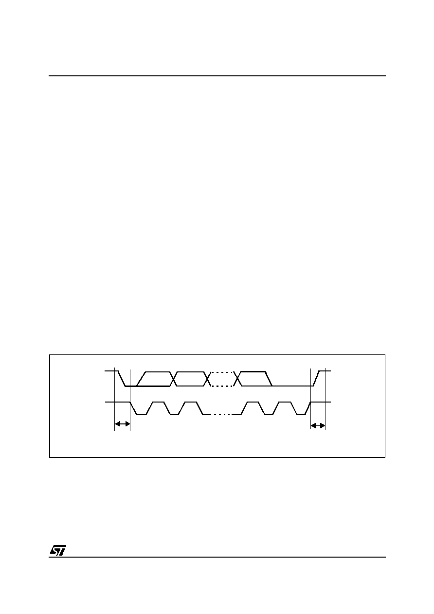
Data and addresses are transferred as 8-bit bytes,
MSB first. The first byte following the start
condition is the address byte.
A 9th clock pulse follows the 8 clock cycles of a
byte transfer, during which the receiver must send
an acknowledge bit to the transmitter. Refer to
Figure 52.
Figure 52. I2C BUS Protocol
SCL
SDA
12
8
9
MSB
ACK
STOP
START
CONDITION
VR02119B
相关PDF资料 |
PDF描述 |
|---|---|
| ST7294C6B6 | 8-BIT, MROM, 4 MHz, MICROCONTROLLER, PDIP28 |
| ST72T94C6M6 | 8-BIT, OTPROM, MICROCONTROLLER, PDSO28 |
| ST72C171K2B6 | 8-BIT, FLASH, 8 MHz, MICROCONTROLLER, PDIP32 |
| ST72E85A5G0 | 8-BIT, UVPROM, 4.332 MHz, MICROCONTROLLER, CQFP80 |
| ST72F321J9T7 | 8-BIT, FLASH, 8 MHz, MICROCONTROLLER, PQFP44 |
相关代理商/技术参数 |
参数描述 |
|---|---|
| ST730 | 制造商:IRF 制造商全称:International Rectifier 功能描述:PHASE CONTROL THYRISTORS Hockey Puk Version |
| ST7-30 | 制造商:SUPERWORLD 制造商全称:Superworld Electronics 功能描述:POWER TRANSFORMER |
| ST-7300 | 制造商:GC Electronics 功能描述: |
| ST730186-3 | 制造商:KEMET Corporation 功能描述: 制造商:KET 功能描述: |
| ST730268-1 | 制造商:KEMET Corporation 功能描述: 制造商:KET 功能描述: |
发布紧急采购,3分钟左右您将得到回复。