- 您现在的位置:买卖IC网 > PDF目录98145 > ST72T774S9T1 (STMICROELECTRONICS) 8-BIT, OTPROM, 8 MHz, MICROCONTROLLER, PQFP44 PDF资料下载
参数资料
| 型号: | ST72T774S9T1 |
| 厂商: | STMICROELECTRONICS |
| 元件分类: | 微控制器/微处理器 |
| 英文描述: | 8-BIT, OTPROM, 8 MHz, MICROCONTROLLER, PQFP44 |
| 封装: | TQFP-44 |
| 文件页数: | 91/144页 |
| 文件大小: | 1280K |
| 代理商: | ST72T774S9T1 |
第1页第2页第3页第4页第5页第6页第7页第8页第9页第10页第11页第12页第13页第14页第15页第16页第17页第18页第19页第20页第21页第22页第23页第24页第25页第26页第27页第28页第29页第30页第31页第32页第33页第34页第35页第36页第37页第38页第39页第40页第41页第42页第43页第44页第45页第46页第47页第48页第49页第50页第51页第52页第53页第54页第55页第56页第57页第58页第59页第60页第61页第62页第63页第64页第65页第66页第67页第68页第69页第70页第71页第72页第73页第74页第75页第76页第77页第78页第79页第80页第81页第82页第83页第84页第85页第86页第87页第88页第89页第90页当前第91页第92页第93页第94页第95页第96页第97页第98页第99页第100页第101页第102页第103页第104页第105页第106页第107页第108页第109页第110页第111页第112页第113页第114页第115页第116页第117页第118页第119页第120页第121页第122页第123页第124页第125页第126页第127页第128页第129页第130页第131页第132页第133页第134页第135页第136页第137页第138页第139页第140页第141页第142页第143页第144页
ST72774/ST727754/ST72734
50/144
16-BIT TIMER (Cont’d)
4.3.3.7 Pulse Width Modulation Mode
Pulse
Width
Modulation
mode
enables
the
generation of a signal with a frequency and pulse
length determined by the value of the OC1R and
OC2R registers.
The pulse width modulation mode uses the
complete Output Compare 1 function plus the
OC2R register.
Procedure
To use pulse width modulation mode select the
following in the CR1 register:
– Using the OLVL1 bit, select the level to be ap-
plied to the OCMP1 pin after a successful com-
parison with OC1R register.
– Using the OLVL2 bit, select the level to be ap-
plied to the OCMP1 pin after a successful com-
parison with OC2R register.
And select the following in the CR2 register:
– Set OC1E bit: the OCMP1 pin is then dedicated
to the output compare 1 function.
– Set the PWM bit.
– Select the timer clock (CC1-CC0) (see Table 15
Clock Control Bits).
Load
the
OC2R
register
with
the
value
corresponding to the period of the signal.
Load
the
OC1R
register
with
the
value
corresponding to the length of the pulse if
(OLVL1=0 and OLVL2=1).
If OLVL1=1 and OLVL2=0 the length of the pulse is
the difference between the OC2R and OC1R
registers.
The OCiR register value required for a specific
timing application can be calculated using the
following formula:
Where:
– t = Desired output compare period (seconds)
–fCPU = Internal clock frequency (see Miscella-
neous register)
– CC1-CC0 = Timer clock prescaler
The Output Compare 2 event causes the counter
to be initialized to FFFCh (See Figure 36).
Note: After a write instruction to the OC
iHR register, the
output compare function is inhibited until the OC
iLR
register is also written.
The OCF1 and OCF2 bits cannot be set by
hardware in PWM mode therefore the Output
Compare interrupt is inhibited. The Input Capture
interrupts are available.
When the Pulse Width Modulation (PWM) and
One Pulse Mode (OPM) bits are both set, the
PWM mode is the only active one.
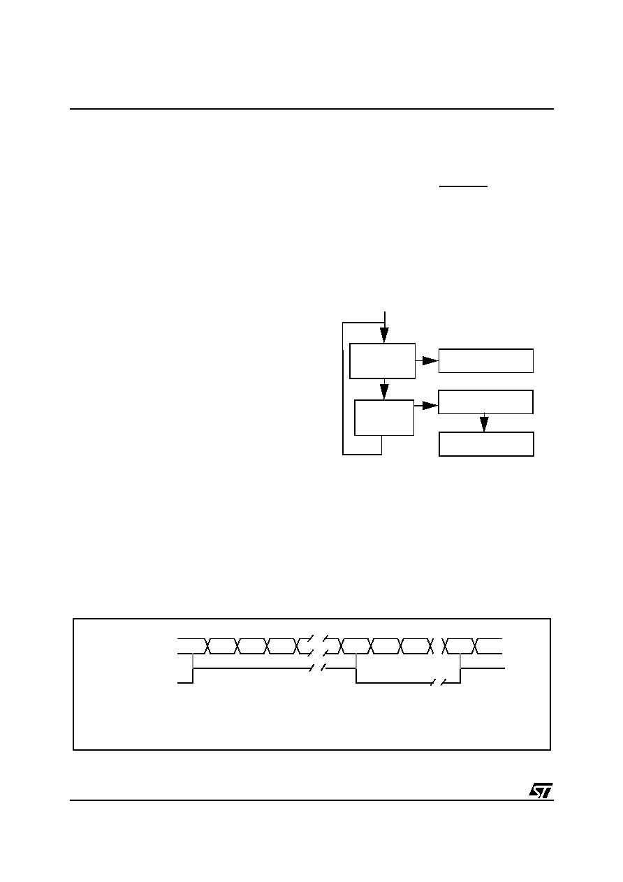
Figure 36. Pulse Width Modulation Mode Timing
OC
iR Value =
t * fCPU
(CC1.CC0)
- 5
Counter
Counter is reset
to FFFCh
OCMP1 = OLVL2
Counter
= OC2R
OCMP1 = OLVL1
When
= OC1R
Pulse Width Modulation cycle
COUNTER
34E2
FFFC FFFD FFFE
2ED0 2ED1 2ED2
34E2
FFFC
OLVL2
OLVL1
OCMP1
compare2
compare1
compare2
Note: OC1R=2ED0h, OC2R=34E2, OLVL1=0, OLVL2= 1
相关PDF资料 |
PDF描述 |
|---|---|
| ST7294C6B6 | 8-BIT, MROM, 4 MHz, MICROCONTROLLER, PDIP28 |
| ST72T94C6M6 | 8-BIT, OTPROM, MICROCONTROLLER, PDSO28 |
| ST72C171K2B6 | 8-BIT, FLASH, 8 MHz, MICROCONTROLLER, PDIP32 |
| ST72E85A5G0 | 8-BIT, UVPROM, 4.332 MHz, MICROCONTROLLER, CQFP80 |
| ST72F321J9T7 | 8-BIT, FLASH, 8 MHz, MICROCONTROLLER, PQFP44 |
相关代理商/技术参数 |
参数描述 |
|---|---|
| ST730 | 制造商:IRF 制造商全称:International Rectifier 功能描述:PHASE CONTROL THYRISTORS Hockey Puk Version |
| ST7-30 | 制造商:SUPERWORLD 制造商全称:Superworld Electronics 功能描述:POWER TRANSFORMER |
| ST-7300 | 制造商:GC Electronics 功能描述: |
| ST730186-3 | 制造商:KEMET Corporation 功能描述: 制造商:KET 功能描述: |
| ST730268-1 | 制造商:KEMET Corporation 功能描述: 制造商:KET 功能描述: |
发布紧急采购,3分钟左右您将得到回复。