参数资料
| 型号: | X98017L128-3.3-Z |
| 厂商: | Intersil |
| 文件页数: | 2/29页 |
| 文件大小: | 0K |
| 描述: | IC VIDEO DIGITIZER TRPL 128MQFP |
| 标准包装: | 66 |
| 类型: | 视频数字转换器,3 通道 AFE |
| 应用: | LCD 电视机/监控器 |
| 安装类型: | 表面贴装 |
| 封装/外壳: | 128-BFQFP |
| 供应商设备封装: | 128-MQFP(14x20) |
| 包装: | 托盘 |
| 产品目录页面: | 1247 (CN2011-ZH PDF) |
第1页当前第2页第3页第4页第5页第6页第7页第8页第9页第10页第11页第12页第13页第14页第15页第16页第17页第18页第19页第20页第21页第22页第23页第24页第25页第26页第27页第28页第29页
10
FN8218.3
March 8, 2006
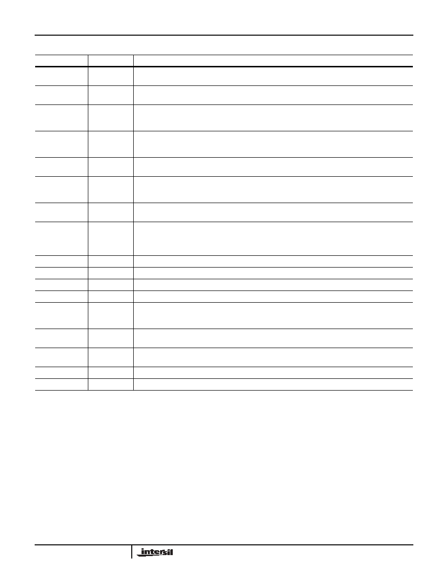
HSOUT
125
3.3V digital output. HSYNC output aligned with pixel data. Use this output to frame the digital output data.
This output is always purely horizontal sync (without any composite sync signals)
VSOUT
126
3.3V digital output.Artificial VSYNC output aligned with pixel data. VSYNC is generated 8 pixel clocks after
the trailing edge of HSOUT. This signal is usually not needed - use VSYNCOUT as VSYNC source.
HSYNCOUT
127
3.3V digital output. Buffered HSYNC (or SOG or CSYNC) output. This is typically used to measure HSYNC
period. HSOUT should be used to detect the beginning of a line. This output will pass composite sync signals
and Macrovision signals if present on HSYNCIN or SOGIN.
VSYNCOUT
128
3.3V digital output. Buffered VSYNC output. For composite sync signals, this output will be asserted for the
duration of the disruption of the normal HSYNC pattern. This is typically used to detect the beginning of a
frame and measure the VSYNC period.
VA
6, 11, 18, 20,
29, 35
Power supply for the analog section. Connect to a 3.3V supply and bypass each pin to GNDA with 0.1F.
GNDA
3, 5, 8, 10, 15,
17, 21, 23, 27,
30, 36
Ground return for VA and VBYPASS.
VD
54, 67, 77, 89,
99, 111, 124
Power supply for all digital I/Os. Connect to a 3.3V supply and bypass each pin to GNDD with 0.1F.
GNDD
32, 43, 51, 53,
66, 76, 78, 88,
98, 108, 110,
120, 123
Ground return for VD, VCORE, VCOREADC, and VPLL.
VX
38
Power supply for crystal oscillator. Connect to a 3.3V supply and bypass to GNDX with 0.1F.
GNDX
37
Ground return for VX.
VBYPASS
4, 9, 16
Bypass these pins to GNDA with 0.1F. Do not connect these pins to each other or anything else.
VREGIN
65
3.3V input voltage for VCORE voltage regulator. Connect to a 3.3V source, and bypass to GNDD with 0.1F.
VREGOUT
64
Regulated output voltage for VPLL, VCOREADC and VCORE; typically 1.9V. Connect only to VPLL,
VCOREADC and VCORE and bypass at input pins as instructed below. Do not connect to anything else - this
output can only supply power to VPLL, VCOREADC and VCORE.
VCOREADC
31
Internal power for the ADC’s digital logic. Connect to VREGOUT through a 10 resistor and bypass to GNDD
with 0.1F.
VPLL
42
Internal power for the PLL’s digital logic. Connect to VREGOUT through a 10 resistor and bypass to GNDD
with 0.1F.
VCORE
52, 79, 109
Internal power for core logic. Connect to VREGOUT and bypass each pin to GNDD with 0.1F.
NC
1, 2, 63
Reserved. Do not connect anything to these pins.
Pin Descriptions (Continued)
SYMBOL
PIN
DESCRIPTION
X98017
相关PDF资料 |
PDF描述 |
|---|---|
| X98021L128-3.3-Z | IC TRPL VID DIGITIZER 128MQFP |
| X98024L128-3.3-Z | IC TRPL VID DIGITIZER 128MQFP |
| X98027L128-3.3-Z | IC TRPL VID DIGITIZER 128MQFP |
| XC25BS5001MR-G | IC CLK BUFFER PLL SOT26 |
| XC25BS7001ER-G | IC CLK GENERATOR PLL USP-6C |
相关代理商/技术参数 |
参数描述 |
|---|---|
| X98021 | 制造商:INTERSIL 制造商全称:Intersil Corporation 功能描述:210MHz Triple Video Digitizer with Digital PLL |
| X98021_06 | 制造商:INTERSIL 制造商全称:Intersil Corporation 功能描述:210MHz Triple Video Digitizer with Digital PLL |
| X98021EVAL | 制造商:Intersil Corporation 功能描述:EVALUATION BOARD FOR X98021 - Bulk |
| X98021L128-3.3 | 制造商:INTERSIL 制造商全称:Intersil Corporation 功能描述:210MHz Triple Video Digitizer with Digital PLL |
| X98021L128-3.3-Z | 功能描述:IC TRPL VID DIGITIZER 128MQFP RoHS:是 类别:集成电路 (IC) >> 线性 - 视频处理 系列:- 标准包装:250 系列:- 类型:电平移位器 应用:LCD 电视机/监控器 安装类型:表面贴装 封装/外壳:28-WFQFN 裸露焊盘 供应商设备封装:28-WQFN(4x4)裸露焊盘 包装:带卷 (TR) 其它名称:296-32523-2TPS65198RUYT-ND |
发布紧急采购,3分钟左右您将得到回复。