参数资料
| 型号: | X98017L128-3.3-Z |
| 厂商: | Intersil |
| 文件页数: | 22/29页 |
| 文件大小: | 0K |
| 描述: | IC VIDEO DIGITIZER TRPL 128MQFP |
| 标准包装: | 66 |
| 类型: | 视频数字转换器,3 通道 AFE |
| 应用: | LCD 电视机/监控器 |
| 安装类型: | 表面贴装 |
| 封装/外壳: | 128-BFQFP |
| 供应商设备封装: | 128-MQFP(14x20) |
| 包装: | 托盘 |
| 产品目录页面: | 1247 (CN2011-ZH PDF) |
第1页第2页第3页第4页第5页第6页第7页第8页第9页第10页第11页第12页第13页第14页第15页第16页第17页第18页第19页第20页第21页当前第22页第23页第24页第25页第26页第27页第28页第29页
29
All Intersil U.S. products are manufactured, assembled and tested utilizing ISO9000 quality systems.
Intersil Corporation’s quality certifications can be viewed at www.intersil.com/design/quality
Intersil products are sold by description only. Intersil Corporation reserves the right to make changes in circuit design, software and/or specifications at any time without
notice. Accordingly, the reader is cautioned to verify that data sheets are current before placing orders. Information furnished by Intersil is believed to be accurate and
reliable. However, no responsibility is assumed by Intersil or its subsidiaries for its use; nor for any infringements of patents or other rights of third parties which may result
from its use. No license is granted by implication or otherwise under any patent or patent rights of Intersil or its subsidiaries.
For information regarding Intersil Corporation and its products, see www.intersil.com
FN8218.3
March 8, 2006
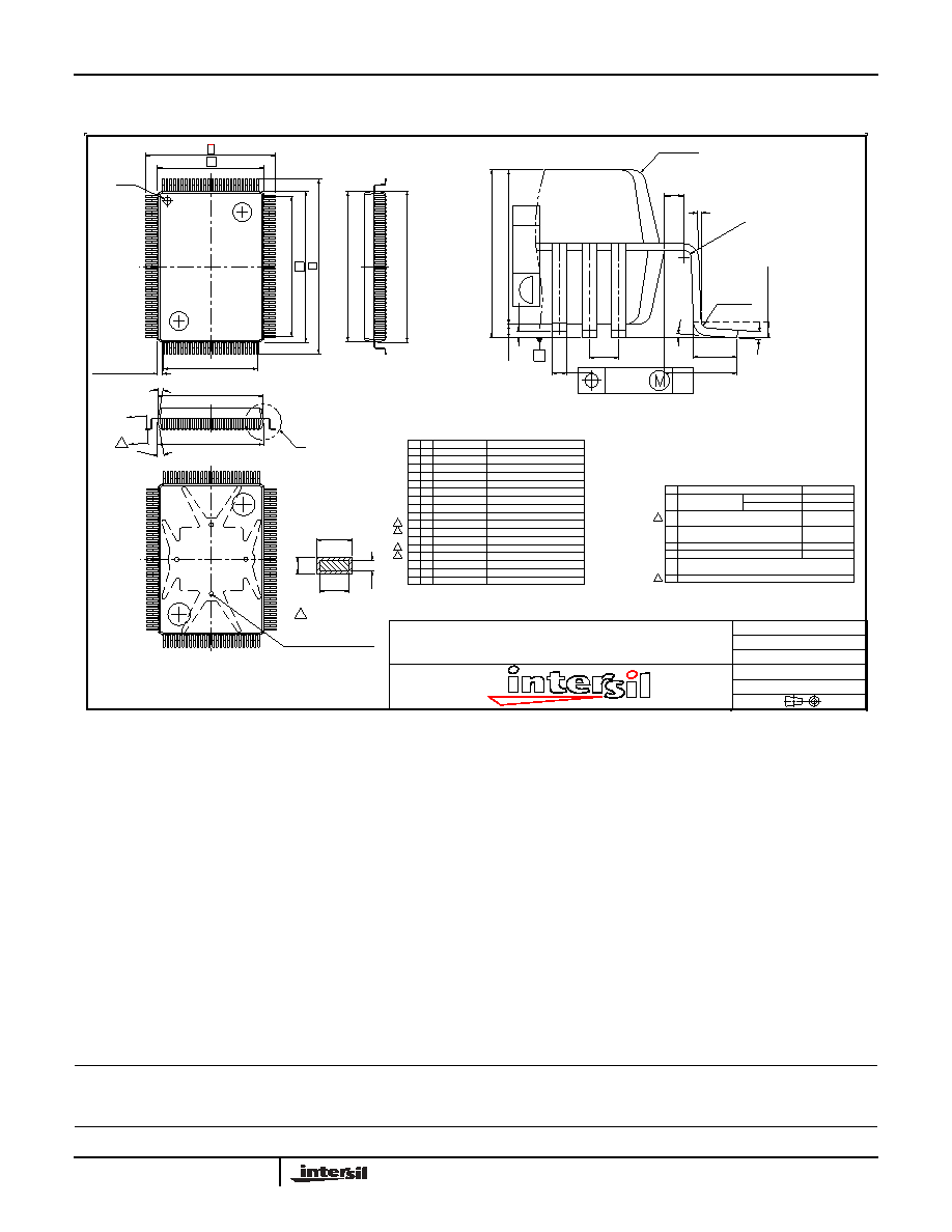
128-Lead Metric Quad Flat Pack (MQFP)
1
2.750±0.250
DIMENSIONS
MAX. 3.40
A
1
S/N
SYM
DIMENSION LIST ( FOOTPRINT: 3.200)
14.000±0.100
23.200±0.250
17.200±0.250
0.250~0.500
0°~7°
1.600 REF.
0.880±0.150
0.170±0.060
0.152±0.040
20.000±0.100
2
D
4
3
5
E
6
L
8
9
1
a
1
12
11
T
10
7
A2
L1
T1
E1
D1
A1
0.500 BASE
0.100
0.200±0.030
e
1
15
14
17
16
1
S/N
GENERAL TOLERANCE.
NOTES :
ddd
ccc
b1
1
0.220±0.050
b
13
2
1
4
3
6
2
7
5
OR CUTTING BURR.
DRAWING DOES NOT INCLUDE PLASTIC OR METAL PROTRUSION
EXCEPT EJECTION AND PIN 1 MARKING.
ALL MOLDED BODY SHARP CORNER RADII
UNLESS OTHERWISE SPECIFIED.
COMPLIANT TO JEDEC STANDARD:
TOP/BTM PACKAGE MISALIGNMENT ( X, Y ):
PACKAGE/LEADFRAME MISALIGNMENT ( X, Y ):
MATTE FINISH ON PACKAGE BODY SURFACE
Ra 0.8~2.0um
MS-022
MAX. R0.200
MAX. 0.127
STANDOFF
SPECIFICATION
LEAD BASE METAL WIDTH
FOOT COPLANARITY
LEAD PITCH
FOOT POSITION
DESCRIPTION
DISTANCE
ANGLE
±0.100
±2.5°
LEAD TIP TO TIP
PKG THICKNESS
LEAD TIP TO TIP
PKG LENGTH
FRAME THICKNESS
LEAD LENGTH
FOOT ANGLE
FOOT LENGTH
PKG WIDTH
FRAME BASE METAL THICKNESS
LEAD WIDTH
OVERALL HEIGHT
REMARKS
SEATING
PLANE
14.000±0.100
ALL AROUND
1
A
12°
(D1)
Y
T
b
13.870±0.100
(4X)
C0.600X0.350
12° ALL AROUND
A
12.500 REF.
D
1
PIN 1
128
D1
18.500
REF.
19.870±0.100
E1
E
(E1)
20.000±0.100
ddd
C
DETAIL Y
C
A1
b
e
L
L1
a
T
0.13~0.30
R0.13
MIN.
ccc
C
.
A
A2
ALL AROUND
R0.25 TYP
0.200 MIN.
0 ° MIN.
GAGE
PLANE
0.25
BASE
SOLUTIONS IN SILICON
PACKAGE OUTLINE DRAWING
14 x 20 mm 128 LEAD MQFP (with or without Heat spreader)
DROP IN HEAT SPREADER
4 STAND POINTS EXPOSED
SECTION A-A
b1
T1
Drawing #: MDP0055
Units: mm
Date: 09/26/05
Rev: 1
3.2 mm FOOTPRINT
X98017
相关PDF资料 |
PDF描述 |
|---|---|
| X98021L128-3.3-Z | IC TRPL VID DIGITIZER 128MQFP |
| X98024L128-3.3-Z | IC TRPL VID DIGITIZER 128MQFP |
| X98027L128-3.3-Z | IC TRPL VID DIGITIZER 128MQFP |
| XC25BS5001MR-G | IC CLK BUFFER PLL SOT26 |
| XC25BS7001ER-G | IC CLK GENERATOR PLL USP-6C |
相关代理商/技术参数 |
参数描述 |
|---|---|
| X98021 | 制造商:INTERSIL 制造商全称:Intersil Corporation 功能描述:210MHz Triple Video Digitizer with Digital PLL |
| X98021_06 | 制造商:INTERSIL 制造商全称:Intersil Corporation 功能描述:210MHz Triple Video Digitizer with Digital PLL |
| X98021EVAL | 制造商:Intersil Corporation 功能描述:EVALUATION BOARD FOR X98021 - Bulk |
| X98021L128-3.3 | 制造商:INTERSIL 制造商全称:Intersil Corporation 功能描述:210MHz Triple Video Digitizer with Digital PLL |
| X98021L128-3.3-Z | 功能描述:IC TRPL VID DIGITIZER 128MQFP RoHS:是 类别:集成电路 (IC) >> 线性 - 视频处理 系列:- 标准包装:250 系列:- 类型:电平移位器 应用:LCD 电视机/监控器 安装类型:表面贴装 封装/外壳:28-WFQFN 裸露焊盘 供应商设备封装:28-WQFN(4x4)裸露焊盘 包装:带卷 (TR) 其它名称:296-32523-2TPS65198RUYT-ND |
发布紧急采购,3分钟左右您将得到回复。