- 您现在的位置:买卖IC网 > PDF目录11763 > XRT94L31IB (Exar Corporation)IC MAPPER DS3/E3/STS-1 504TBGA PDF资料下载
参数资料
| 型号: | XRT94L31IB |
| 厂商: | Exar Corporation |
| 文件页数: | 45/133页 |
| 文件大小: | 0K |
| 描述: | IC MAPPER DS3/E3/STS-1 504TBGA |
| 标准包装: | 24 |
| 应用: | 网络切换 |
| 接口: | 总线 |
| 电源电压: | 3.14 V ~ 3.47 V |
| 封装/外壳: | 504-LBGA |
| 供应商设备封装: | 504-TBGA(35x35) |
| 包装: | 托盘 |
| 安装类型: | 表面贴装 |
第1页第2页第3页第4页第5页第6页第7页第8页第9页第10页第11页第12页第13页第14页第15页第16页第17页第18页第19页第20页第21页第22页第23页第24页第25页第26页第27页第28页第29页第30页第31页第32页第33页第34页第35页第36页第37页第38页第39页第40页第41页第42页第43页第44页当前第45页第46页第47页第48页第49页第50页第51页第52页第53页第54页第55页第56页第57页第58页第59页第60页第61页第62页第63页第64页第65页第66页第67页第68页第69页第70页第71页第72页第73页第74页第75页第76页第77页第78页第79页第80页第81页第82页第83页第84页第85页第86页第87页第88页第89页第90页第91页第92页第93页第94页第95页第96页第97页第98页第99页第100页第101页第102页第103页第104页第105页第106页第107页第108页第109页第110页第111页第112页第113页第114页第115页第116页第117页第118页第119页第120页第121页第122页第123页第124页第125页第126页第127页第128页第129页第130页第131页第132页第133页
XRT94L31
19
REV. 1.0.1
3-CHANNEL DS3/E3/STS-1 TO STS-3/STM-1 MAPPER IC
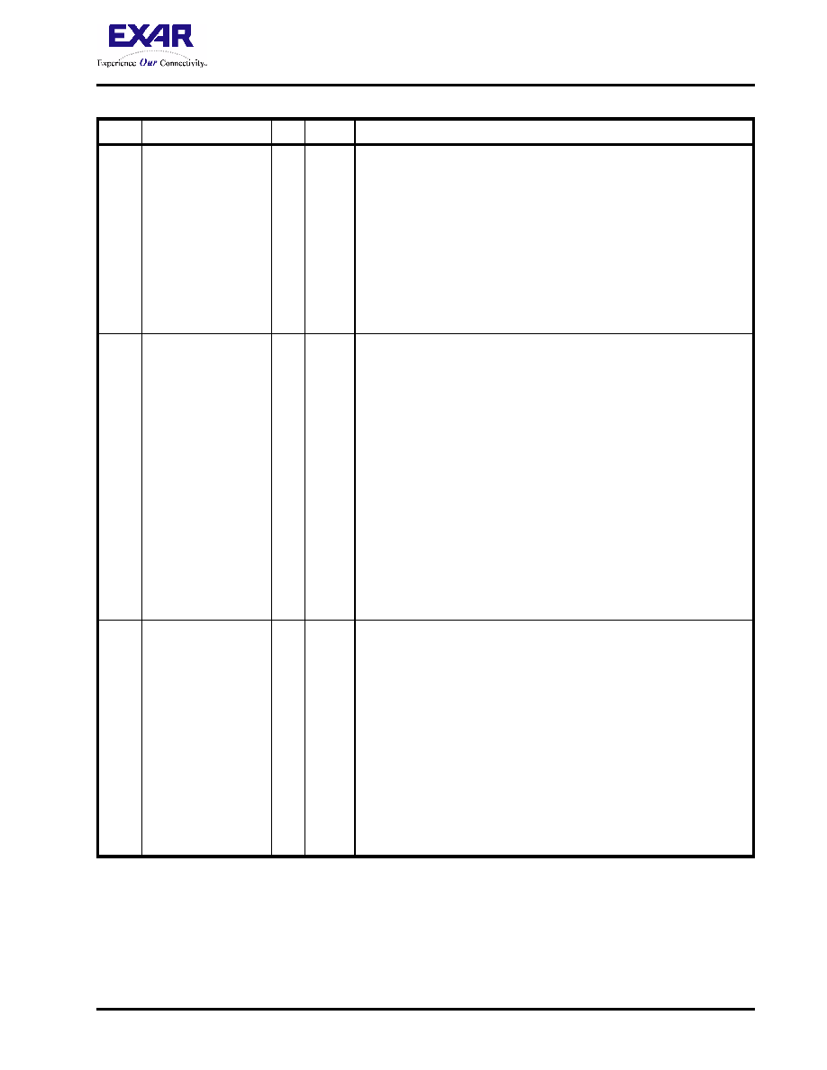
AD1
RxD_C1J1
I
TTL
Receive STS-3/STM-1 Telecom Bus Interface - C1/J1 Byte Phase
Indicator Input Signal:
This input pin should be pulsed "High" during both of the following condi-
tions.
a. Coincident to whenever the C1/J0 byte (within the incoming STS-
3/STM-1 signal) is being applied to the Receive STS-3/STM-1
Telecom Bus - Data Input pins (RXD_D[7:0]).
b. Coincident to whenever the J1 byte(s) (within the incoming STS-3/
STM-1 signal) is being applied to the Receive STS-3/STM-1
Telecom Bus - Data Input pins (RXD_D[7:0]) input.
NOTE: This input pin should be pulled "Low" during all other times.
AB3
RxD_DP
I
TTL
Receive STS-3/STM-1 Telecom Bus Interface - Parity Input pin:
This input pin can be configured to function as one of the following.
The EVEN or ODD parity value of the bits (within the incoming STS-3/
STM-1 signal) which are currently being input via the RXD_D[7:0] input
pins.
The EVEN or ODD parity value of the bits (within the incoming STS-3/
STM-1 signal) which are being input via the RXD_D[7:0] input and the
states of the RXD_PL and RXD_C1J1 input pins.
The Receive STS-3/STM-1 Telecom Bus Interface block will use this
input signal to compute and verify the Parity of each byte within the
incoming STS-3/STM-1 data-stream.
NOTES:
1. Any one of these configuration selections can be made by
writing the appropriate value into the Telecom Bus Control
register (Address Location = 0x0137).
2. Tie this input pin to GND if the STS-3/STM-1 Telecom Bus
Interface is disabled.
W1
RxD_ALARM
I
TTL
Receive STS-3/STM-1 Telecom Bus Interface - Alarm Indicator
Input:
This input pin should be pulsed "High" for one RxD_CLK period coinci-
dent to whenever the Receive STS-3/STM-1 Telecom Bus Interface is
accepting a byte from an incoming STS-1 or STS-3c signal (via the
RxD_D[7:0] input pins) that is carrying the AIS-P indicator.
This input pin should be held at a logic "Low" at all other times.
NOTES:
1. If the RxD_ALARM input signal pulses "High" for any given
STS-1 signal (within the incoming STS-3), the XRT94L31 will
automatically declare the AIS-P defect condition for that STS-1
or STS-3c channel.
2. Tie this input pin to GND, if the STS-3/STM-1 Telecom Bus
Interface is disabled.
PIN DESCRIPTION OF THE XRT94L31 (REV. B)
PIN #
SIGNAL NAME
I/O
TYPE
DESCRIPTION
相关PDF资料 |
PDF描述 |
|---|---|
| 413985-1 | CONN PLUG SMB RG-174 STR GOLD |
| VI-B4P-IW-F1 | CONVERTER MOD DC/DC 13.8V 100W |
| 413589-9 | CONN PLUG BNC RG-59 CRIMP GOLD |
| MS27473T20B1PB | CONN PLUG 79POS STRAIGHT W/PINS |
| 1408149-3 | CONN MMCX PLUG RT ANG RD-316 |
相关代理商/技术参数 |
参数描述 |
|---|---|
| XRT94L31IB-F | 功能描述:网络控制器与处理器 IC Demapper RoHS:否 制造商:Micrel 产品:Controller Area Network (CAN) 收发器数量: 数据速率: 电源电流(最大值):595 mA 最大工作温度:+ 85 C 安装风格:SMD/SMT 封装 / 箱体:PBGA-400 封装:Tray |
| XRT94L31IB-L | 功能描述:网络控制器与处理器 IC Mapper / Demapper RoHS:否 制造商:Micrel 产品:Controller Area Network (CAN) 收发器数量: 数据速率: 电源电流(最大值):595 mA 最大工作温度:+ 85 C 安装风格:SMD/SMT 封装 / 箱体:PBGA-400 封装:Tray |
| XRT94L33 | 制造商:EXAR 制造商全称:EXAR 功能描述:-CHANNEL DS3/E3/STS-1 TO STS-3/STM-1 MAPPER - SONET REGISTERS |
| XRT94L33_06 | 制造商:EXAR 制造商全称:EXAR 功能描述:3-CHANNEL DS3/E3/STS-1 TO STS-3/STM-1 MAPPER IC DATA SHEET |
| XRT94L33_07 | 制造商:EXAR 制造商全称:EXAR 功能描述:3-CHANNEL DS3/E3/STS-1 TO STS-3/STM-1 MAPPER - ATM REGISTERS |
发布紧急采购,3分钟左右您将得到回复。