- 您现在的位置:买卖IC网 > PDF目录20665 > ZL2105EVK2 (Intersil)EVAL BOARD 2 ZL2105 PDF资料下载
参数资料
| 型号: | ZL2105EVK2 |
| 厂商: | Intersil |
| 文件页数: | 11/36页 |
| 文件大小: | 0K |
| 描述: | EVAL BOARD 2 ZL2105 |
| 标准包装: | 1 |
| 系列: | * |
第1页第2页第3页第4页第5页第6页第7页第8页第9页第10页当前第11页第12页第13页第14页第15页第16页第17页第18页第19页第20页第21页第22页第23页第24页第25页第26页第27页第28页第29页第30页第31页第32页第33页第34页第35页第36页
�� �
�
�ZL2105�
�4.2� Power� Conversion� Overview�
�>�
�INPUT� VOLTAGE� BUS�
�>�
�PG�
�EN�
�MGN� ILIM� DLY�
�SS�
�CFG� V(0,1)�
�BST�
�VTRK�
�POWER� MANAGEMENT�
�NVM�
�I� SENSE�
�LDO�
�FC�
�DIGITAL�
�COMPENSATOR�
�D-PWM�
�MOSFET�
�SW�
�V� OUT�
�SYNC�
�GEN�
�NLR�
�DRIVERS�
�SYNC�
�PLL�
�ADC�
�-�
�VDR�
�+�
�RESET�
�REF�
�ADC�
�VDD�
�I� SENSE�
�VR�
�CHG�
�PUMP�
�CP1�
�CP2�
�VSEN�
�SALRT�
�SDA�
�SCL�
�SA�
�COMMUNICATION�
�ADC�
�MUX�
�TEMP�
�SENSOR�
�XTEMP�
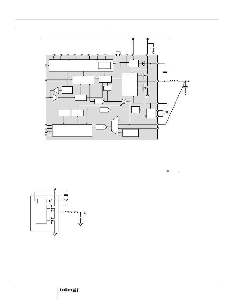
�Figure� 5.� ZL2105� Block� Diagram�
�The� ZL2105� operates� as� a� voltage-mode,� synchronous�
�buck� converter� with� a� selectable� constant� frequency�
�is� known� as� the� duty� cycle� D� ,� which� is� described� by� the�
�following� equation:�
�PWM� control� scheme.� The� ZL2105� incorporates� dual�
�low� R� DS(ON)� synchronous� MOSFETs� to� help� minimize�
�the� required� circuit� footprint.�
�D�
�V� OUT�
�V� IN�
�V� IN�
�C� IN�
�During� time� D,� QH� is� on� and� V� IN� –� V� OUT� is� applied�
�across� the� inductor.�
�As� shown� in� Figure� 5,� the� output� voltage� is� directly�
�LDO�
�D� B�
�QH�
�C� B�
�L� 1�
�applied� to� the� VSEN� pin.� The� VSEN� signal� is� then�
�compared� to� an� internal� programmable� reference�
�voltage� that� is� set� to� the� desired� output� voltage� level.�
�PWM�
�QL�
�V� OUT�
�C� OUT�
�The� error� signal� derived� from� this� comparison� is�
�converted� to� a� digital� value� with� a� fast� analog� to� digital�
�(A/D)� converter.� The� digital� signal� is� also� applied� to� an�
�ZL2105�
�adjustable� digital� compensation�
�filter,� and� the�
�compensated� signal� is� used� to� derive� the� appropriate�
�Figure� 6.� Synchronous� Buck� Converter�
��converter� topology� showing� the� primary� power� train�
�components.� This� converter� is� also� called� a� step-down�
�converter,� as� the� output� voltage� must� always� be� lower�
�than� the� input� voltage.� The� ZL2105� integrates� two�
�MOSFETs;� QH� is� the� top� control� MOSFET� and� QL� is�
�the� bottom� synchronous� MOSFET.� The� amount� of� time�
�that� QH� is� on� as� a� fraction� of� the� total� switching� period�
�11�
�PWM� duty� cycle� for� driving� the� internal� MOSFETs.�
�The� ZL2105� also� incorporates� a� non-linear� response�
�(NLR)� loop� to� improve� the� response� time� and� reduce�
�the� output� deviation� as� a� result� of� a� load� transient.� The�
�ZL21� 05� monitors� the� power� converter’s� operating�
�conditions� and� continuously� adjusts� the� turn-on� and�
�turn-off� timing� of� the� high-side� and� low-side�
�MOSFETs� to� optimize� the� overall� efficiency� of� the�
�power� supply.�
�FN6851.2�
�March� 30,� 2011�
�相关PDF资料 |
PDF描述 |
|---|---|
| RCM06DRMI | CONN EDGECARD 12POS .156 SQ WW |
| ISL6263CEVAL1 | EVAL BOARD 1 FOR ISL6263C |
| AISC-1008F-6R8G-T | INDUCTOR 6800NH 360MA 2% SMD |
| MAX4211AEUE+T | IC CURRENT MONITOR 1.5% 16TSSOP |
| TC1303A-ZS0EUNTR | IC REG DL BCK/LINEAR SYNC 10MSOP |
相关代理商/技术参数 |
参数描述 |
|---|---|
| ZL2106 | 制造商:INTERSIL 制造商全称:Intersil Corporation 功能描述:6A Digital-DC Synchronous Step-Down DC/DC Converter |
| ZL2106_10 | 制造商:INTERSIL 制造商全称:Intersil Corporation 功能描述:6A Digital-DC Synchronous Step-Down DC/DC Converter |
| ZL2106ALBNT | 制造商:INTERSIL 制造商全称:Intersil Corporation 功能描述:6A Digital-DC Synchronous Step-Down DC-DC Converter |
| ZL2106ALBNT1 | 制造商:INTERSIL 制造商全称:Intersil Corporation 功能描述:6A Digital-DC Synchronous Step-Down DC-DC Converter |
| ZL2106ALCF | 功能描述:直流/直流开关转换器 6A DIGTL DC-DC CNVRT W/DDC BULK50 RoHS:否 制造商:STMicroelectronics 最大输入电压:4.5 V 开关频率:1.5 MHz 输出电压:4.6 V 输出电流:250 mA 输出端数量:2 最大工作温度:+ 85 C 安装风格:SMD/SMT |
发布紧急采购,3分钟左右您将得到回复。