- 您现在的位置:买卖IC网 > PDF目录68810 > 71M6511-IGTR/F (MAXIM INTEGRATED PRODUCTS INC) 1-CHANNEL POWER SUPPLY MANAGEMENT CKT, PQFP64 PDF资料下载
参数资料
| 型号: | 71M6511-IGTR/F |
| 厂商: | MAXIM INTEGRATED PRODUCTS INC |
| 元件分类: | 电源管理 |
| 英文描述: | 1-CHANNEL POWER SUPPLY MANAGEMENT CKT, PQFP64 |
| 封装: | LEAD FREE, LQFP-64 |
| 文件页数: | 13/98页 |
| 文件大小: | 1278K |
| 代理商: | 71M6511-IGTR/F |
第1页第2页第3页第4页第5页第6页第7页第8页第9页第10页第11页第12页当前第13页第14页第15页第16页第17页第18页第19页第20页第21页第22页第23页第24页第25页第26页第27页第28页第29页第30页第31页第32页第33页第34页第35页第36页第37页第38页第39页第40页第41页第42页第43页第44页第45页第46页第47页第48页第49页第50页第51页第52页第53页第54页第55页第56页第57页第58页第59页第60页第61页第62页第63页第64页第65页第66页第67页第68页第69页第70页第71页第72页第73页第74页第75页第76页第77页第78页第79页第80页第81页第82页第83页第84页第85页第86页第87页第88页第89页第90页第91页第92页第93页第94页第95页第96页第97页第98页
71M6511/71M6511H
Single-Phase Energy Meter IC
DATA SHEET
NOVEMBER 2010
Page: 20 of 98
2005–2010 Teridian Semiconductor Corporation
V2.7
A Maxim Integrated Products Brand
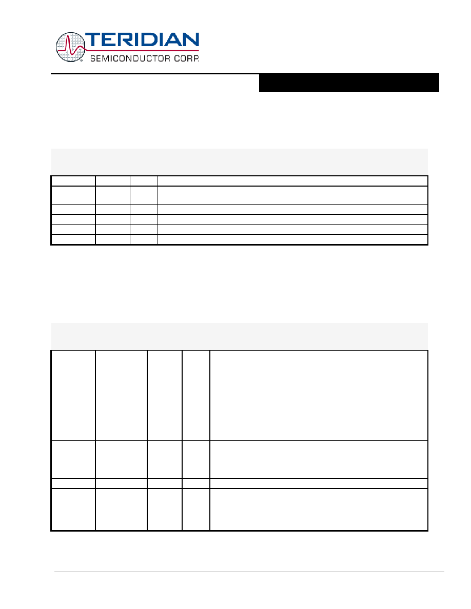
Port Registers: The I/O ports are controlled by Special Function Registers P0, P1, and P2. The contents of the SFR can be
observed on corresponding pins on the chip. Writing a ‘1’ to any of the ports (see Table 11) causes the corresponding pin to
be at high level (V3P3), and writing a ‘0’ causes the corresponding pin to be held at low level (GND). The data direction
registers DIR0, DIR1, and DIR2 define individual pins as input or output pins (see section On-Chip Resources – DIO Ports for
details).
Register
SFR
Addres
s
R/W
Description
P0
0x80
R/W
Register for port 0 read and write operations (pins DIO4…DIO7)
DIR0
0xA2
R/W
Data direction register for port 0. Setting a bit to 1 means that the corresponding pin is
an output.
P1
0x90
R/W
Register for port 1 read and write operations (pins DIO8…DIO15)
DIR1
0x91
R/W
Data direction register for port 1.
P2
0xA0
R/W
Register for port 2 read and write operations (pins DIO16-DIO17)
DIR2
0xA1
R/W
Data direction register for port 2.
Table 11: Port Registers
All four ports on the chip are bi-directional. Each of them consists of a Latch (SFR ‘P0’ to ‘P3’), an output driver, and an input
buffer, therefore the MPU can output or read data through any of these ports. Even if a DIO pin is configured as an output, the
state of the pin can still be read by the MPU, for example when counting pulses issued via DIO pins that are under CE control.
Special Function Registers Specific to the 71M6511
Table 12 shows the location and description of the 71M6511-specific SFRs.
Register
Alternative
Name
SFR
Addres
s
R/W
Description
ERASE
FLSH_ERASE
0x94
W
This register is used to initiate either the Flash Mass Erase cycle or
the Flash Page Erase cycle. Specific patterns are expected for
FLSH_ERASE in order to initiate the appropriate Erase cycle (default =
0x00).
0x55 – Initiate Flash Page Erase cycle. Must be proceeded by a write
to FLSH_PGADR @ SFR 0xB7.
0xAA – Initiate Flash Mass Erase cycle. Must be proceeded by a
write to FLSH_MEEN @ SFR 0xB2 and the debug port must
be enabled.
Any other pattern written to FLSH_ERASE will have no effect.
PGADDR
FLSH_PGADR
0xB7
R/W
Flash Page Erase Address register containing the flash memory
page address (page 0 thru 127) that will be erased during the Page
Erase cycle (default = 0x00).
Must be re-written for each new Page Erase cycle.
EEDATA
0x9E
R/W
I2C EEPROM interface data register
EECTRL
0x9F
R/W
I2C EEPROM interface control register. If the MPU wishes to write a
byte of data to EEPROM, it places the data in EEDATA and then
writes the ‘Transmit’ code to EECTRL. The write to EECTRL initiates
the transmit sequence. See the section I2C Interface (EEPROM) for
a description of the command and status bits available for EECTRL.
相关PDF资料 |
PDF描述 |
|---|---|
| 71M6511-IGT/F | 1-CHANNEL POWER SUPPLY MANAGEMENT CKT, PQFP64 |
| 71M6511-IGT | 1-CHANNEL POWER SUPPLY MANAGEMENT CKT, PQFP64 |
| 71M6511-IGTR | 1-CHANNEL POWER SUPPLY MANAGEMENT CKT, PQFP64 |
| 71M6511H-IGTR/F | 1-CHANNEL POWER SUPPLY MANAGEMENT CKT, PQFP64 |
| 71M6511H-IGT/F | 1-CHANNEL POWER SUPPLY MANAGEMENT CKT, PQFP64 |
相关代理商/技术参数 |
参数描述 |
|---|---|
| 71M6512-DB | 制造商:Maxim Integrated Products 功能描述:Development Boards & Kits - 8051 71M6512 Demo Brd |
| 71M6512-IM/F | 制造商:Maxim Integrated Products 功能描述:Metering Systems on a Chip - SoC Residential Meter Extended Io |
| 71M6512-IMR/F | 制造商:Maxim Integrated Products 功能描述:Metering Systems on a Chip - SoC Residential Meter Extended Io |
| 71M6512-TGQ1-68M | 功能描述:程序设计器配件 Gang Programmer Base Unit+6512 Socket Brd RoHS:否 制造商:Lattice 产品:ispDOWNLOAD Cables 用于:In-system Programming |
| 71M6513 | 制造商:未知厂家 制造商全称:未知厂家 功能描述:71M6513 |
发布紧急采购,3分钟左右您将得到回复。