参数资料
| 型号: | AD73322LYRZ |
| 厂商: | Analog Devices Inc |
| 文件页数: | 20/48页 |
| 文件大小: | 0K |
| 描述: | IC ANALOG FRONT END DUAL 28-SOIC |
| 标准包装: | 27 |
| 位数: | 16 |
| 通道数: | 4 |
| 功率(瓦特): | 73mW |
| 电压 - 电源,模拟: | 2.7 V ~ 5.5 V |
| 电压 - 电源,数字: | 2.7 V ~ 5.5 V |
| 封装/外壳: | 28-SOIC(0.295",7.50mm 宽) |
| 供应商设备封装: | 28-SOIC W |
| 包装: | 管件 |
第1页第2页第3页第4页第5页第6页第7页第8页第9页第10页第11页第12页第13页第14页第15页第16页第17页第18页第19页当前第20页第21页第22页第23页第24页第25页第26页第27页第28页第29页第30页第31页第32页第33页第34页第35页第36页第37页第38页第39页第40页第41页第42页第43页第44页第45页第46页第47页第48页
AD73322L
Rev. A | Page 27 of 48
INTERFACING
The AD73322L can be interfaced to most modern DSP engines
using conventional serial port connections and an extra enable
control line. Both serial input and output data use an accom-
panying frame synchronization signal that is active high one
clock cycle before the start of the 16-bit word or during the last
bit of the previous word if transmission is continuous. The
serial clock (SCLK) is an output from the codec and is used
to define the serial transfer rate to the DSP’s Tx and Rx ports.
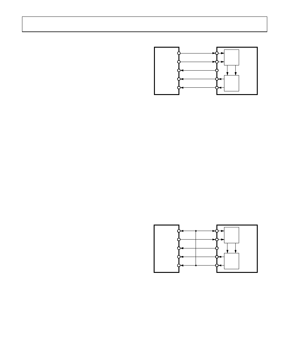
Two primary configurations can be used: the first is shown in
Figure 22 where the DSP’s Tx data, Tx frame sync, Rx data, and
Rx frame sync are connected to the codec’s SDI, SDIFS, SDO,
and SDOFS, respectively. This configuration, referred to as
indirectly coupled or nonframe sync loop-back, has the effect of
decoupling the transmission of input data from the receipt of
output data. The delay between receipt of codec output data and
transmission of input data for the codec is determined by the
DSP’s software latency.
When programming the DSP serial port for this configuration,
it is necessary to set the Rx FS as an input and the Tx FS as an
output generated by the DSP. This configuration is most useful
when operating in mixed mode, as the DSP has the ability to
decide how many words (either DAC or control) can be sent to
the codecs. This means that full control can be implemented
over the device configuration as well as updating the DAC in a
given sample interval.
The second configuration (shown in Figure 24) has the DSP’s
Tx data and Rx data connected to the codec’s SDI and SDO,
respectively, while the DSP’s Tx and Rx frame syncs are
connected to the codec’s SDIFS and SDOFS. In this
configuration, referred to as directly coupled or frame sync
loop-back, the frame sync signals are connected together and
the input data to the codec is forced to be synchronous with the
output data from the codec. The DSP must be programmed so
that both the Tx FS and Rx FS are inputs as the codec SDOFS is
input to both. This configuration guarantees that input and
output events occur simultaneously and is the simplest
configuration for operation in normal data mode. When
programming the DSP in this configuration, it is advisable to
preload the Tx register with the first control word to be sent
before the codec is taken out of reset. This ensures that this
word is transmitted to coincide with the first output word from
the device(s).
TFS
DT
SCLK
DR
RFS
ADSP-21xx
DSP
AD73322L
CODEC
CODEC1
CODEC2
SDIFS
SDI
SCLK
SDO
SDOFS
00691-023
Figure 23. Indirectly Coupled or Nonframe Sync
Loop-Back Configuration
CASCADE OPERATION
The AD73322L has been designed to support cascading of
codecs from a single DSP serial port (see Figure 36). Cascaded
operation can support mixes of dual- or single-channel devices
with the maximum number of codec units being eight (the
AD73322L is equivalent to two codec units). The SPORT
interface protocol has been designed so that device addressing
is built into the packet of information sent to the device. This
allows the cascade to be formed with no extra hardware
overhead for control signals or addressing. A cascade can be
formed in either of the two modes previously discussed.
There may be some restrictions in cascade operation due to the
number of devices configured in the cascade and the sampling
rate and serial clock rate chosen. The following relationship
details the restrictions in configuring a codec cascade.
Number of Codes × Word Size (16) × Sampling Rate ≤
Serial Clock Rate
00691-024
TFS
DT
SCLK
DR
RFS
ADSP-21xx
DSP
AD73322L
CODEC
CODEC1
CODEC2
SDIFS
SDI
SCLK
SDO
SDOFS
Figure 24. Directly Coupled or Frame Sync Loop-Back Configuration
When using the indirectly coupled frame sync configuration
in cascaded operation, be aware of the restrictions in sending
data to all devices in the cascade. Effectively the time allowed is
given by the sampling interval (M/DMCLK—where M can be
256, 512, 1024, or 2048), which is 125 s for a sample rate of
8 kHz. In this interval, the DSP must transfer N × 16 bits of
information where N is the number of devices in the cascade.
相关PDF资料 |
PDF描述 |
|---|---|
| AD73360ARZ | IC PROCESSOR FRONTEND 6CH 28SOIC |
| AD7352YRUZ-500RL7 | IC ADC DUAL 12BIT 3MSPS 16TSSOP |
| AD7356YRUZ-500RL7 | IC ADC DUAL 12BIT 5MSPS 16TSSOP |
| AD7357YRUZ | IC ADC DUAL14BIT 4.2MSPS 16TSSOP |
| AD7367BRUZ-500RL7 | IC ADC 14BIT SAR 1MSPS 24TSSOP |
相关代理商/技术参数 |
参数描述 |
|---|---|
| AD73322LYST | 制造商:Analog Devices 功能描述: |
| AD73322LYSTZ | 制造商:Rochester Electronics LLC 功能描述: 制造商:Analog Devices 功能描述: |
| AD73360 | 制造商:AD 制造商全称:Analog Devices 功能描述:Six-Input Channel Analog Front End |
| AD73360AR | 制造商:Analog Devices 功能描述:AFE General Purpose 6ADC 16-Bit 5V 28-Pin SOIC W 制造商:Analog Devices 功能描述:IC 16-BIT ADC |
| AD73360AR-REEL | 制造商:Analog Devices 功能描述:AFE General Purpose 6ADC 16-Bit 5V 28-Pin SOIC W T/R 制造商:Analog Devices 功能描述:AFE GEN PURPOSE 6ADC 16BIT 5V/5V/5V 28SOIC W - Tape and Reel |
发布紧急采购,3分钟左右您将得到回复。