- 您现在的位置:买卖IC网 > PDF目录10149 > AD7712ARZ-REEL (Analog Devices Inc)IC ADC 24BIT SGNL CONDTNR 24SOIC PDF资料下载
参数资料
| 型号: | AD7712ARZ-REEL |
| 厂商: | Analog Devices Inc |
| 文件页数: | 3/28页 |
| 文件大小: | 0K |
| 描述: | IC ADC 24BIT SGNL CONDTNR 24SOIC |
| 标准包装: | 1,000 |
| 位数: | 24 |
| 采样率(每秒): | 1.03k |
| 数据接口: | 串行 |
| 转换器数目: | 1 |
| 功率耗散(最大): | 45mW |
| 电压电源: | 模拟和数字,双 ± |
| 工作温度: | -40°C ~ 85°C |
| 安装类型: | 表面贴装 |
| 封装/外壳: | 24-SOIC(0.295",7.50mm 宽) |
| 供应商设备封装: | 24-SOIC W |
| 包装: | 带卷 (TR) |
| 输入数目和类型: | 1 个单端,单极;1 个差分,单极;1 个差分,双极 |
第1页第2页当前第3页第4页第5页第6页第7页第8页第9页第10页第11页第12页第13页第14页第15页第16页第17页第18页第19页第20页第21页第22页第23页第24页第25页第26页第27页第28页
REV. F
AD7712
–11–
Tables I and II show the output rms noise for some typical
notch and –3 dB frequencies. The numbers given are for the
bipolar input ranges with a VREF of 2.5 V. These numbers are
typical and are generated with an analog input voltage of 0 V.
The output noise from the part comes from two sources. First,
there is the electrical noise in the semiconductor devices used in
the implementation of the modulator (device noise). Second,
when the analog input signal is converted into the digital do-
main, quantization noise is added. The device noise is at a low
level and is largely independent of frequency. The quantization
noise starts at an even lower level but rises rapidly with increasing
frequency to become the dominant noise source. Consequently,
lower filter notch settings (below 60 Hz approximately) tend to
be device noise dominated while higher notch settings are domi-
nated by quantization noise. Changing the filter notch and cutoff
frequency in the quantization noise dominated region results in a
more dramatic improvement in noise performance than it does
in the device noise dominated region as shown in Table I.
Furthermore, quantization noise is added after the PGA, so
effective resolution is independent of gain for the higher filter
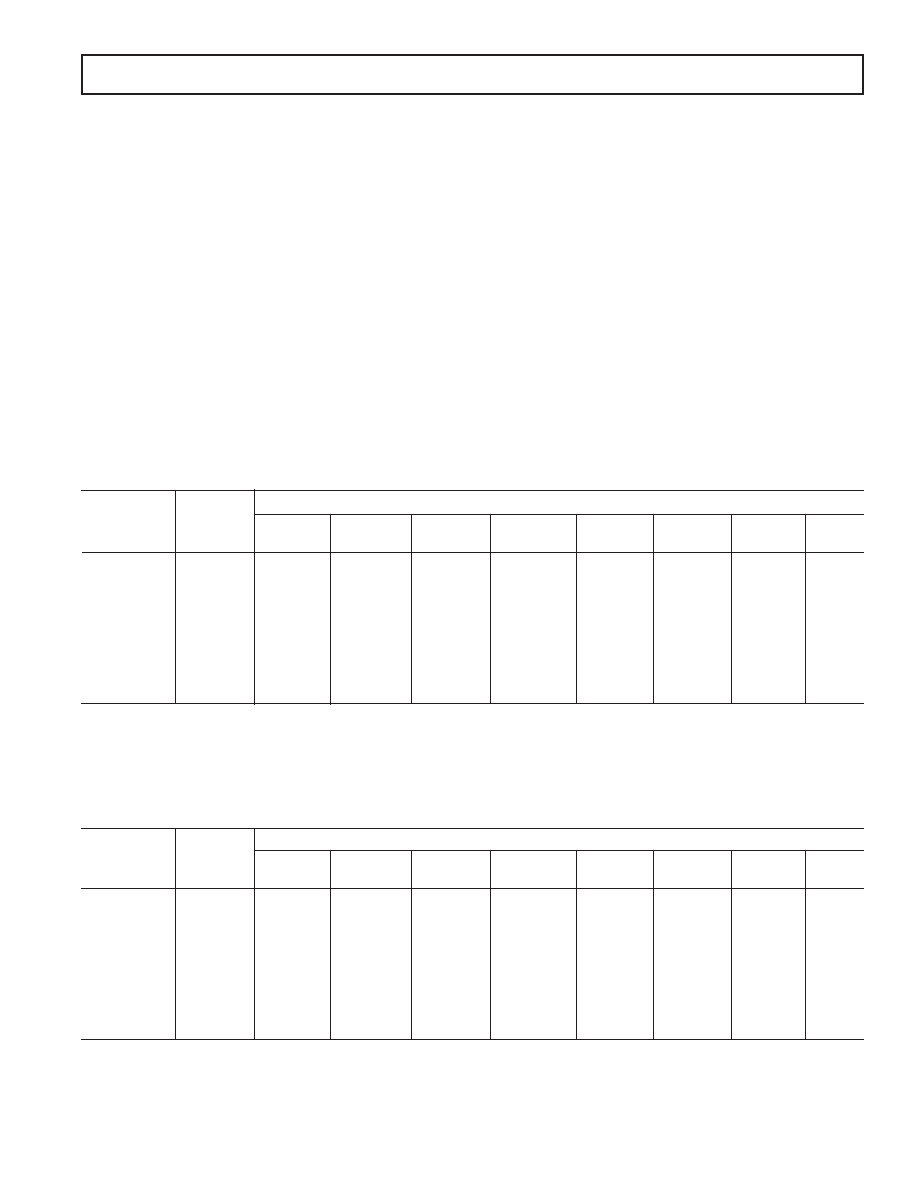
Table I. Output Noise vs. Gain and First Notch Frequency
First Notch of
Filter and O/P –3 dB
Gain of
Data Rate
1
Frequency 124816
32
64
128
10 Hz
2
2.62 Hz
1.0
0.78
0.48
0.33
0.25
25 Hz
2
6.55 Hz
1.8
1.1
0.63
0.5
0.44
0.41
0.38
30 Hz
2
7.86 Hz
2.5
1.31
0.84
0.57
0.46
0.43
0.4
50 Hz
2
13.1 Hz
4.33
2.06
1.2
0.64
0.54
0.46
60 Hz
2
15.72 Hz
5.28
2.36
1.33
0.87
0.63
0.62
0.6
0.56
100 Hz
3
26.2 Hz
13
6.4
3.7
1.8
1.1
0.9
0.65
250 Hz
3
65.5 Hz
130
75
25
12
7.5
4
2.7
1.7
500 Hz
3
131 Hz
0.6
10
3
0.26
10
3
140
70
35
25
15
8
1 kHz
3
262 Hz
3.1
10
3
1.6
10
3
0.7
10
3
0.29
10
3
180
120
70
40
NOTES
1The default condition (after the internal power-on reset) for the first notch of filter is 60 Hz.
2For these filter notch frequencies, the output rms noise is primarily dominated by device noise, and, as a result, is independent of the value of the reference voltage.
Therefore, increasing the reference voltage will give an increase in the effective resolution of the device (i.e., the ratio of the rms noise to the input full scale is
increased since the output rms noise remains constant as the input full scale increases).
3For these filter notch frequencies, the output rms noise is dominated by quantization noise, and, as a result, is proportional to the value of the reference voltage.
Table II. Effective Resolution vs. Gain and First Notch Frequency
First Notch of
Filter and O/P –3 dB
Gain of
Data Rate
Frequency
124816
32
64
128
10 Hz
2.62 Hz
22.5
21.5
21
20.5
19.5
18.5
17.5
25 Hz
6.55 Hz
21.5
21
20
19.5
18.5
17.5
16.5
30 Hz
7.86 Hz
21
20.5
20
19.5
18.5
17.5
16.5
50 Hz
13.1 Hz
20
19
18.5
17.5
16.5
60 Hz
15.72 Hz
20
19.5
19
18
17
16
100 Hz
26.2 Hz
18.5
18
17.5
17
16
250 Hz
65.5 Hz
15
15.5
15
14.5
500 Hz
131 Hz
13
12.5
1 kHz
262 Hz
10.5
11
10.5
10
*Effective resolution is defined as the magnitude of the output rms noise with respect to the input full scale (i.e., 2
VREF/GAIN). The above table applies for
a VREF of 2.5 V and resolution numbers are rounded to the nearest 0.5 LSB.
Typical Output RMS Noise ( V)
Effective Resolution
* (Bits)
notch frequencies. Meanwhile, device noise is added in the PGA
and, therefore, effective resolution suffers a little at high gains
for lower notch frequencies.
At the lower filter notch settings (below 60 Hz), the no missing
codes performance of the device is at the 24-bit level. At the
higher settings, more codes will be missed until at the 1 kHz
notch setting; no missing codes performance is guaranteed only
to the 12-bit level. However, since the effective resolution of the
part is 10.5 bits for this filter notch setting, this no missing codes
performance should be more than adequate for all applications.
The effective resolution of the device is defined as the ratio of
the output rms noise to the input full scale. This does not
remain constant with increasing gain or with increasing band-
width. Table II is the same as Table I except that the output is
expressed in terms of effective resolution (the magnitude of the
rms noise with respect to 2
VREF/GAIN, i.e., the input full
scale). It is possible to do post filtering on the device to improve
the output data rate for a given –3 dB frequency and to further
reduce the output noise (see the Digital Filtering section).
相关PDF资料 |
PDF描述 |
|---|---|
| VE-2NN-MX-F4 | CONVERTER MOD DC/DC 18.5V 75W |
| D38999/20WB98SA | CONN RCPT 6POS WALL MNT W/SCKT |
| PXA911/04/P | CONN PLUG 4POS W/PINS LG CABLE |
| VE-2NN-MX-F3 | CONVERTER MOD DC/DC 18.5V 75W |
| VE-B30-IV-F2 | CONVERTER MOD DC/DC 5V 150W |
相关代理商/技术参数 |
参数描述 |
|---|---|
| AD7712ARZ-REEL7 | 功能描述:IC ADC 24BIT SGNL CONDTNR 24SOIC RoHS:是 类别:集成电路 (IC) >> 数据采集 - 模数转换器 系列:- 标准包装:1 系列:- 位数:14 采样率(每秒):83k 数据接口:串行,并联 转换器数目:1 功率耗散(最大):95mW 电压电源:双 ± 工作温度:0°C ~ 70°C 安装类型:通孔 封装/外壳:28-DIP(0.600",15.24mm) 供应商设备封装:28-PDIP 包装:管件 输入数目和类型:1 个单端,双极 |
| AD7712EB | 制造商:AD 制造商全称:Analog Devices 功能描述:LC 2 MOS Signal Conditioning ADC(229.08 k) |
| AD7712SQ | 制造商:Analog Devices 功能描述: 制造商:Rochester Electronics LLC 功能描述:24 BIT SIGMA DELTA ADC IC - Bulk |
| AD7713 | 制造商:AD 制造商全称:Analog Devices 功能描述:LC2MOS Loop-Powered Signal Conditioning ADC |
发布紧急采购,3分钟左右您将得到回复。