- 您现在的位置:买卖IC网 > PDF目录4596 > ADE5166ASTZF62-RL (Analog Devices Inc)IC METER/8052/RTC/LCD DRV 64LQFP PDF资料下载
参数资料
| 型号: | ADE5166ASTZF62-RL |
| 厂商: | Analog Devices Inc |
| 文件页数: | 134/156页 |
| 文件大小: | 0K |
| 描述: | IC METER/8052/RTC/LCD DRV 64LQFP |
| 产品变化通告: | Product Discontinuance 27/Oct/2011 |
| 标准包装: | 1,500 |
| 输入阻抗: | * |
| 测量误差: | * |
| 电压 - 高输入/输出: | * |
| 电压 - 低输入/输出: | * |
| 电流 - 电源: | * |
| 电源电压: | * |
| 测量仪表类型: | * |
| 工作温度: | * |
| 安装类型: | 表面贴装 |
| 封装/外壳: | 64-LQFP |
| 供应商设备封装: | 64-LQFP(10x10) |
| 包装: | 带卷 (TR) |
第1页第2页第3页第4页第5页第6页第7页第8页第9页第10页第11页第12页第13页第14页第15页第16页第17页第18页第19页第20页第21页第22页第23页第24页第25页第26页第27页第28页第29页第30页第31页第32页第33页第34页第35页第36页第37页第38页第39页第40页第41页第42页第43页第44页第45页第46页第47页第48页第49页第50页第51页第52页第53页第54页第55页第56页第57页第58页第59页第60页第61页第62页第63页第64页第65页第66页第67页第68页第69页第70页第71页第72页第73页第74页第75页第76页第77页第78页第79页第80页第81页第82页第83页第84页第85页第86页第87页第88页第89页第90页第91页第92页第93页第94页第95页第96页第97页第98页第99页第100页第101页第102页第103页第104页第105页第106页第107页第108页第109页第110页第111页第112页第113页第114页第115页第116页第117页第118页第119页第120页第121页第122页第123页第124页第125页第126页第127页第128页第129页第130页第131页第132页第133页当前第134页第135页第136页第137页第138页第139页第140页第141页第142页第143页第144页第145页第146页第147页第148页第149页第150页第151页第152页第153页第154页第155页第156页
�� �
�
�ADE5166/ADE5169/ADE5566/ADE5569�
�Data� Sheet�
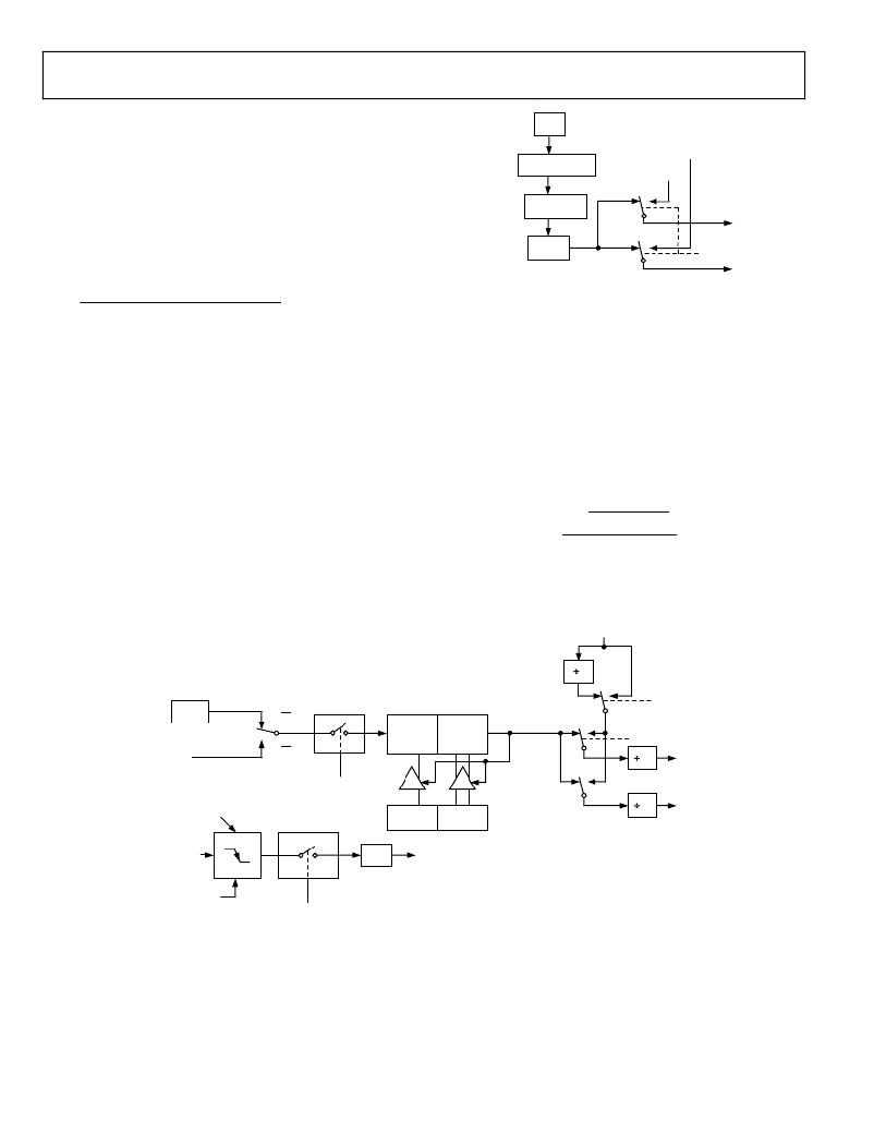
�Because� Timer� 2� has� 16-bit� autoreload� capability,� very� low� baud�
�rates� are� still� possible.� Timer� 2� is� selected� as� the� baud� rate� generator�
�f� CORE�
�TIMER� 1/TIMER� 2�
�by� setting� RCLK� and/or� TCLK� in� the� Timer/Counter� 2� control�
�SFR� (T2CON,� Address� 0xC8[5:4]).� The� baud� rates� for� transmit�
�and� receive� can� be� simultaneously� different.� Setting� RCLK� and/or�
�FRACTIONAL�
�DIVIDER�
�÷(1� +� SBAUDF/64)�
�Tx� CLOCK�
�TIMER� 1/TIMER� 2�
�Rx� CLOCK�
�1�
�0�
�TCLK� puts� Timer� 2� into� its� baud� rate� generator� mode,� as� shown� in�
�Figure� 108.�
�÷2� DIV� +� SBTH�
�Rx� CLOCK�
�In� this� case,� the� baud� rate� is� given� by� the� following� formula:�
�Mode� 1� or� Mode� 3� Baud� Rate� =�
�÷32�
�1�
�UART� TIMER�
�Rx/Tx� CLOCK�
�0�
�UARTBAUDEN�
�Tx� CLOCK�
�f� CORE�
�log� ?�
�?�
�log� (� 2� )�
�f� CORE�
�(� 16� � [� 65536� ?� (� RCAP� 2� H� :� RCAP� 2� L� )� ]� )�
�UART� Timer� Generated� Baud� Rates�
�The� high� integer� dividers� in� a� UART� block� mean� that� high� speed�
�baud� rates� are� not� always� possible.� In� addition,� generating� baud�
�rates� requires� the� exclusive� use� of� a� timer,� rendering� it� unusable�
�for� other� applications� when� the� UART� is� required.� To� address�
�this� problem,� each� ADE5166/ADE5169/ADE5566/ADE5569�
�has� a� dedicated� baud� rate� timer� (UART� timer)� specifically� for�
�generating� highly� accurate� baud� rates.� The� UART� timer� can� be�
�used� instead� of� Timer� 1� or� Timer� 2� for� generating� very� accurate�
�high� speed� UART� baud� rates,� including� 115,200� bps.� This� timer�
�also� allows� a� much� wider� range� of� baud� rates� to� be� obtained.� In�
�fact,� every� desired� bit� rate� from� 12� bps� to� 393,216� bps� can� be�
�generated� to� within� an� error� of� ±0.8%.� The� UART� timer� also�
�Figure� 107.� UART� Timer,� UART� Baud� Rate�
�Two� SFRs,� the� enhanced� serial� baud� rate� control� SFR� (SBAUDT,�
�Address� 0x9E)� and� UART� timer� fractional� divider� SFR� (SBAUDF,�
�Address� 0x9D),� are� used� to� control� the� UART� timer.� SBAUDT�
�is� the� baud� rate� control� SFR;� it� sets� up� the� integer� divider� (the� DIV�
�bits,� Bits[2:0])� and� the� extended� divider� (the� SBTH� bits,� Bits[4:3])�
�for� the� UART� timer.�
�The� appropriate� value� to� write� to� the� DIV� bits� and� the� SBTH�
�bits� can� be� calculated� using� the� following� formula,� where� f� CORE� is�
�defined� in� the� POWCON� SFR� (see� Table� 26).� Note� that� the� DIV�
�value� must� be� rounded� down� to� the� nearest� integer.�
�?� ?�
�?� ?�
�?� 16� � Baud� Rate� ?�
�DIV� +� SBTH� =�
�frees� up� the� other� three� timers,� allowing� them� to� be� used� for�
�different� applications.� A� block� diagram� of� the� UART� timer� is�
�shown� in� Figure� 107.�
�TIMER� 1�
�OVERFLOW�
�2�
�0�
�1�
�f� CORE�
�C/� T2� =� 0�
�CONTROL�
�TIMER� 2�
�SMOD�
�TL2�
�(8� BITS)�
�TH2�
�(8� BITS)�
�OVERFLOW�
�1�
�0�
�RCLK�
�T2� PIN�
�(P1.4/T2/FP23)�
�C/� T2� =� 1�
�1�
�0�
�16�
�Rx�
�CLOCK�
�TR2�
�TCLK�
�NOTE:� AVAILABILITY� OF� ADDITIONAL�
�EXTERNAL� INTERRUPT�
�RCAP2L�
�RCAP2H�
�RELOAD�
�16�
�Tx�
�CLOCK�
�T2EX� PIN�
�(P1.3/T2EX/FP24)�
�TRANSITION�
�CONTROL�
�EXF� 2�
�TIMER� 2�
�INTERRUPT�
�P1.4/T2/FP23�
�DETECTOR�
�EXEN2�
�Figure� 108.� Timer� 2,� UART� Baud� Rates�
�Rev.� D� |� Page� 134� of� 156�
�相关PDF资料 |
PDF描述 |
|---|---|
| ADE5166ASTZF62 | IC METER/8052/RTC/LCD DRV 64LQFP |
| NCP699SN28T1G | IC REG LDO 2.8V 240MA 5TSOP |
| RSC50DRYN-S13 | CONN EDGECARD 100POS .100 EXTEND |
| LFEC3E-4QN208I | IC FPGA 3.1KLUTS 208PQFP |
| KSZ8995MAI | IC SWITCH 5-PORT 10/100 128PQFP |
相关代理商/技术参数 |
参数描述 |
|---|---|
| ADE5169 | 制造商:AD 制造商全称:Analog Devices 功能描述:Single-Phase Energy Measurement IC with 8052 MCU, RTC, and LCD Driver |
| ADE5169ASTZF62 | 功能描述:IC METER/8052/RTC/LCD DR 64LQFP RoHS:是 类别:集成电路 (IC) >> PMIC - 能量测量 系列:- 产品培训模块:Lead (SnPb) Finish for COTS Obsolescence Mitigation Program 标准包装:2,500 系列:* |
| ADE5169ASTZF62-RL | 功能描述:IC METER/8052/RTC/LCD DRV 64LQFP RoHS:是 类别:集成电路 (IC) >> PMIC - 能量测量 系列:- 产品培训模块:Lead (SnPb) Finish for COTS Obsolescence Mitigation Program 标准包装:2,500 系列:* |
| ADE5566 | 制造商:AD 制造商全称:Analog Devices 功能描述:Single-Phase Energy Measurement IC with 8052 MCU, RTC, and LCD Driver |
| ADE5566ASTZF62 | 功能描述:IC ENERGY METERING 1PHASE 64LQFP RoHS:是 类别:集成电路 (IC) >> PMIC - 能量测量 系列:- 产品培训模块:Lead (SnPb) Finish for COTS Obsolescence Mitigation Program 标准包装:2,500 系列:* |
发布紧急采购,3分钟左右您将得到回复。