参数资料
| 型号: | ADV7180WBCPZ |
| 厂商: | Analog Devices Inc |
| 文件页数: | 53/116页 |
| 文件大小: | 0K |
| 描述: | IC VIDEO DECODER SDTV 40LFCSP |
| 标准包装: | 1 |
| 类型: | 视频解码器 |
| 应用: | 数码相机,手机,便携式视频 |
| 安装类型: | 表面贴装 |
| 封装/外壳: | 40-VFQFN 裸露焊盘,CSP |
| 供应商设备封装: | 40-LFCSP-VQ(6x6) |
| 包装: | 托盘 |
第1页第2页第3页第4页第5页第6页第7页第8页第9页第10页第11页第12页第13页第14页第15页第16页第17页第18页第19页第20页第21页第22页第23页第24页第25页第26页第27页第28页第29页第30页第31页第32页第33页第34页第35页第36页第37页第38页第39页第40页第41页第42页第43页第44页第45页第46页第47页第48页第49页第50页第51页第52页当前第53页第54页第55页第56页第57页第58页第59页第60页第61页第62页第63页第64页第65页第66页第67页第68页第69页第70页第71页第72页第73页第74页第75页第76页第77页第78页第79页第80页第81页第82页第83页第84页第85页第86页第87页第88页第89页第90页第91页第92页第93页第94页第95页第96页第97页第98页第99页第100页第101页第102页第103页第104页第105页第106页第107页第108页第109页第110页第111页第112页第113页第114页第115页第116页
Data Sheet
ADV7180
Rev. I | Page 41 of 116
DIGITAL NOISE REDUCTION (DNR) AND LUMA
PEAKING FILTER
Digital noise reduction is based on the assumption that high
frequency signals with low amplitude are probably noise and
that, therefore, their removal improves picture quality. The
following are the two DNR blocks in the ADV7180: the DNR1
block before the luma peaking filter and the DNR2 block after
the luma peaking filter, as shown in Figure 32.
LUMA
OUTPUT
DNR1
LUMA PEAKING
FILTER
DNR2
LUMA
SIGNAL
05700-
051
Figure 32. DNR and Peaking Block Diagram
DNR_EN, Digital Noise Reduction Enable, Address 0x4D[5]
The DNR_EN bit enables the DNR block or bypasses it.
Table 49. DNR_EN Function
Setting
Description
0
Bypasses DNR (disable)
1 (default)
Enables digital noise reduction on the luma data
DNR_TH[7:0], DNR Noise Threshold, Address 0x50[7:0]
The DNR1 block is positioned before the luma peaking block.
The DNR_TH[7:0] value is an unsigned, 8-bit number used to
determine the maximum edge that is interpreted as noise and,
therefore, blanked from the luma data. Programming a large
value into DNR_TH[7:0] causes the DNR block to interpret
even large transients as noise and remove them. As a result, the
effect on the video data is more visible. Programming a small
value causes only small transients to be seen as noise and to be
removed.
Table 50. DNR_TH[7:0] Function
Setting
Description
0x08 (default)
Threshold for maximum luma edges to be
interpreted as noise
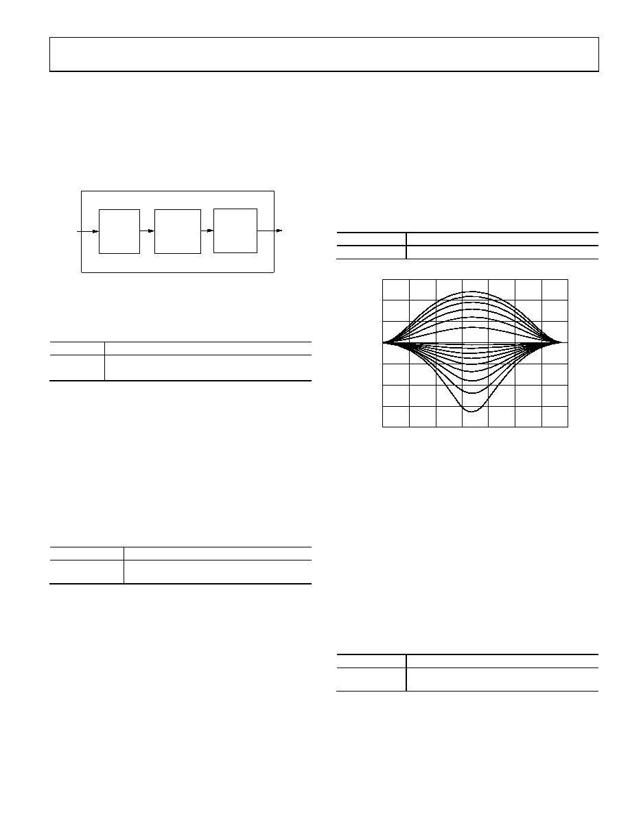
PEAKING_GAIN[7:0], Luma Peaking Gain,
Address 0xFB[7:0]
This filter can be manually enabled. The user can select to boost
or to attenuate the mid region of the Y spectrum around 3 MHz.
The peaking filter can visually improve the picture by showing
more definition on the picture details that contain frequency
components around 3 MHz. The default value on this register
passes through the luma data unaltered. A lower value attenuates
the signal, and a higher value gains the luma signal. A plot of
the responses of the filter is shown in Figure 33.
Table 51. PEAKING_GAIN[7:0] Function
Setting
Description
0x40 (Default)
0 dB response
15
–20
07
05
70
0-
05
2
FREQUENCY (MHz)
F
IL
T
ER
R
E
SPO
N
SE
(
d
B
)
10
5
0
–5
–10
–15
12
34
56
PEAKING GAIN USING BP FILTER
Figure 33. Peaking Filter Responses
DNR_TH2[7:0], DNR Noise Threshold 2,
Address 0xFC[7:0]
The DNR2 block is positioned after the luma peaking block
and, therefore, affects the gained luma signal. It operates in the
same way as the DNR1 block, but there is an independent
threshold control, DNR_TH2[7:0], for this block. This value is
an unsigned, 8-bit number used to determine the maximum
edge that is interpreted as noise and, therefore, blanked from
the luma data. Programming a large value into DNR_TH2[7:0]
causes the DNR block to interpret even large transients as noise
and remove them. As a result, the effect on the video data is more
visible. Programming a small value causes only small transients
to be seen as noise and to be removed.
Table 52. DNR_TH2[7:0] Function
Setting
Description
0x04 (default)
Threshold for maximum luma edges to be
interpreted as noise
相关PDF资料 |
PDF描述 |
|---|---|
| ADV7186BBCZ | IC VIDEO DECODER 196CSPBGA |
| ADV7441ABSTZ-5P | IC DECODER DIGITIZER 144LQFP |
| ADV7513BSWZ | IC TX HDMI 165MHZ 64LQFP |
| ADV7520BCPZ-80 | IC XMITTER HDMI/DVI CEC 64LFCSP |
| ADV7520NKBBCZ-80 | IC XMITTER HDMI/DVI LP 76CSPBGA |
相关代理商/技术参数 |
参数描述 |
|---|---|
| ADV7180WBCPZ-REEL | 功能描述:IC VIDEO DECODER SDTV 40LFCSP RoHS:是 类别:集成电路 (IC) >> 线性 - 视频处理 系列:- 产品变化通告:Product Discontinuation 07/Mar/2011 标准包装:3,000 系列:OMNITUNE™ 类型:调谐器 应用:移动电话,手机,视频显示器 安装类型:表面贴装 封装/外壳:65-WFBGA 供应商设备封装:PG-WFSGA-65 包装:带卷 (TR) 其它名称:SP000365064 |
| ADV7180WBST48Z | 制造商:Analog Devices 功能描述: |
| ADV7180WBST48Z-RL | 功能描述:视频 IC 10-bit 4x Oversampling SDTV Decoder RoHS:否 制造商:Fairchild Semiconductor 工作电源电压:5 V 电源电流:80 mA 最大工作温度:+ 85 C 封装 / 箱体:TSSOP-28 封装:Reel |
| ADV7180WBSTZ | 功能描述:视频 IC 10-bit 4x Oversampling SDTV Decoder RoHS:否 制造商:Fairchild Semiconductor 工作电源电压:5 V 电源电流:80 mA 最大工作温度:+ 85 C 封装 / 箱体:TSSOP-28 封装:Reel |
| ADV7180WBSTZ-REEL | 功能描述:视频 IC 10-bit 4x Oversampling SDTV Decoder RoHS:否 制造商:Fairchild Semiconductor 工作电源电压:5 V 电源电流:80 mA 最大工作温度:+ 85 C 封装 / 箱体:TSSOP-28 封装:Reel |
发布紧急采购,3分钟左右您将得到回复。