- 您现在的位置:买卖IC网 > PDF目录298892 > B80547RE061256 (INTEL CORP) 32-BIT, 2530 MHz, MICROPROCESSOR, PBGA775 PDF资料下载
参数资料
| 型号: | B80547RE061256 |
| 厂商: | INTEL CORP |
| 元件分类: | 微控制器/微处理器 |
| 英文描述: | 32-BIT, 2530 MHz, MICROPROCESSOR, PBGA775 |
| 封装: | FLIP CHIP, LGA-775 |
| 文件页数: | 8/94页 |
| 文件大小: | 2796K |
| 代理商: | B80547RE061256 |
第1页第2页第3页第4页第5页第6页第7页当前第8页第9页第10页第11页第12页第13页第14页第15页第16页第17页第18页第19页第20页第21页第22页第23页第24页第25页第26页第27页第28页第29页第30页第31页第32页第33页第34页第35页第36页第37页第38页第39页第40页第41页第42页第43页第44页第45页第46页第47页第48页第49页第50页第51页第52页第53页第54页第55页第56页第57页第58页第59页第60页第61页第62页第63页第64页第65页第66页第67页第68页第69页第70页第71页第72页第73页第74页第75页第76页第77页第78页第79页第80页第81页第82页第83页第84页第85页第86页第87页第88页第89页第90页第91页第92页第93页第94页
16
Datasheet
Electrical Specifications
2.3.1
VCC Decoupling
Regulator solutions need to provide bulk capacitance with a low Effective Series Resistance (ESR)
and keep a low interconnect resistance from the regulator to the socket. Bulk decoupling for the
large current swings when the part is powering on, or entering/exiting low power states, must be
provided by the voltage regulator solution (VR). For more details, refer to the Voltage Regulator
Down (VRD) 10.1 Design Guide For Desktop LGA775 Socket.
2.3.2
FSB GTL+ Decoupling
The Celeron D processor in the 775-land package integrates signal termination on the die as well as
incorporating high frequency decoupling capacitance on the processor package. Decoupling must
also be provided by the system baseboard for proper GTL+ bus operation.
2.3.3
FSB Clock (BCLK[1:0]) and Processor Clocking
BCLK[1:0] directly controls the FSB interface speed as well as the core frequency of the processor.
As in previous generation processors, the Celeron D processor in the 775-land package core
frequency is a multiple of the BCLK[1:0] frequency. Refer to Table 2-1 for the Celeron D
processor in the 775-land package supported ratios.
The Celeron D processor in the 775-land package uses a differential clocking implementation. For
more information on the Celeron D processor in the 775-land package clocking, refer to the
CK410/CK410M Clock Synthesizer/Driver Specification.
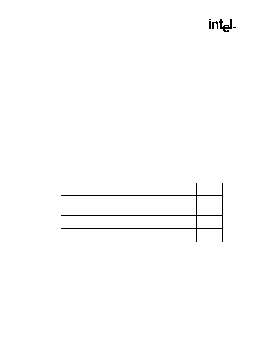
Table 2-1. Core Frequency to FSB Multiplier Configuration
Multiplication of System Core
Frequency to FSB Frequency
Processor
Number
Core Frequency (133 MHz BCLK
/ 533 MHz FSB)
Notes1
NOTES:
1.
Individual processors operate only at or below the rated frequency.
1/19
325J/326
2.53 GHz
—
1/20
330J/331
2.66 GHz
—
1/21
335J/336
2.80 GHz
—
1/22
340J/341
2.93 GHz
—
1/23
345J/346
3.06 GHz
—
1/24
351
3.20 GHz
—
1/25
355
3.33 GHz
—
相关PDF资料 |
PDF描述 |
|---|---|
| B80547RE077256 | 32-BIT, 2930 MHz, MICROPROCESSOR, PBGA775 |
| BX80547RE2933C | 32-BIT, 2930 MHz, MICROPROCESSOR, PBGA775 |
| BX80547RE3330CN | 32-BIT, 3330 MHz, MICROPROCESSOR, CBGA775 |
| BX80547RE2533C | 32-BIT, 2530 MHz, MICROPROCESSOR, PBGA775 |
| BX80547RE2667C | 32-BIT, 2600 MHz, MICROPROCESSOR, PBGA775 |
相关代理商/技术参数 |
参数描述 |
|---|---|
| B8055 | 功能描述:函数发生器与合成器 Function Generator 5MHz RoHS:否 制造商:Tektronix 频率:20 MHz 设备类型:Function Generators |
| B-80-6 | 制造商:Hozan Tool Industrial Co Ltd 功能描述: |
| B8062N | 制造商:Laird Technologies Inc 功能描述:WHIP,MC,1/2,806-899 MHZ |
| B8062NCO | 功能描述:ACCY MISC RC B8062N ANTENNA RoHS:是 类别:RF/IF 和 RFID >> RF配件 系列:* 标准包装:1 系列:* |
| B8063 | 制造商:Laird Technologies Inc 功能描述:WHIP,MC,5/8,806-866 MHZ |
发布紧急采购,3分钟左右您将得到回复。