- 您现在的位置:买卖IC网 > PDF目录256054 > BU-65843F3-200 (DATA DEVICE CORP) 2 CHANNEL(S), 1M bps, MIL-STD-1553 CONTROLLER, CQFP80 PDF资料下载
参数资料
| 型号: | BU-65843F3-200 |
| 厂商: | DATA DEVICE CORP |
| 元件分类: | 微控制器/微处理器 |
| 英文描述: | 2 CHANNEL(S), 1M bps, MIL-STD-1553 CONTROLLER, CQFP80 |
| 封装: | 0.880 INCH, CERAMIC, QFP-80 |
| 文件页数: | 32/75页 |
| 文件大小: | 532K |
| 代理商: | BU-65843F3-200 |
第1页第2页第3页第4页第5页第6页第7页第8页第9页第10页第11页第12页第13页第14页第15页第16页第17页第18页第19页第20页第21页第22页第23页第24页第25页第26页第27页第28页第29页第30页第31页当前第32页第33页第34页第35页第36页第37页第38页第39页第40页第41页第42页第43页第44页第45页第46页第47页第48页第49页第50页第51页第52页第53页第54页第55页第56页第57页第58页第59页第60页第61页第62页第63页第64页第65页第66页第67页第68页第69页第70页第71页第72页第73页第74页第75页
38
Data Device Corporation
www.ddc-web.com
BU-65743/65843/65863/65864
D-06/04-0
WORD MONITOR MODE
In the Word Monitor Terminal mode, the PCI Mini-ACE
Mark3/Micro-ACE TE monitors both 1553 buses. After the soft-
ware initialization and Monitor Start sequences, the PCI Mini-
ACE Mark3/Micro-ACE TE stores all Command, Status, and
Data Words received from both buses. For each word received
from either bus, a pair of words is stored to the PCI Mini-ACE
Mark3/Micro-ACE TE's shared RAM. The first word is the word
received from the 1553 bus. The second word is the Monitor
Identification (ID), or "Tag" word. The ID word contains informa-
tion relating to bus channel, word validity, and inter-word time
gaps. The data and ID words are stored in a circular buffer in the
shared RAM address space.
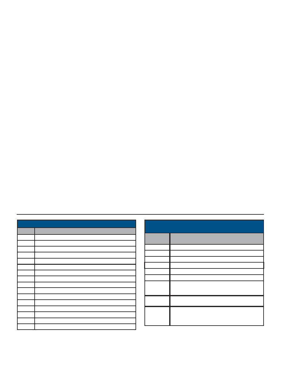
WORD MONITOR MEMORY MAP
A typical word monitor memory map is illustrated in TABLE 59.
TABLE 59 assumes a 64K address space for the PCI Mini-ACE
Mark3/Micro-ACE TE's monitor. The Active Area Stack pointer
provides the address where the first monitored word is stored. In
the example, it is assumed that the Active Area Stack Pointer for
Area A (location 0100) is initialized to 0000. The first received
data word is stored in location 0000, the ID word for the first word
is stored in location 0001, etc.
The current Monitor address is maintained by means of a
counter register. This value may be read by the CPU by means
of the Data Stack Address Register. It is important to note that
when the counter reaches the Stack Pointer address of 0100 or
0104, the initial pointer value stored in this shared RAM location
will be overwritten by the monitored data and ID Words. When
the internal counter reaches an address of FFFF (or 0FFF, for an
PCI Mini-ACE Mark3/Micro-ACE TE with 4K RAM), the counter
rolls over to 0000.
WORD MONITOR TRIGGER
In the Word Monitor mode, there is a pattern recognition trigger
and a pattern recognition interrupt. The 16-bit compare word for
both the trigger and the interrupt is stored in the Monitor Trigger
Word Register. The pattern recognition interrupt is enabled by set-
ting the MT Pattern Trigger bit in Interrupt Mask Register. The pat-
tern recognition trigger is enabled by setting the Trigger Enable bit
in Configuration Register #1 and selecting either the Start-on-trig-
ger or the Stop-on-trigger bit in Configuration Register #1. The
Word Monitor may also be started by means of a low-to-high
transition on the EXT_TRIG input signal.
SELECTIVE MESSAGE MONITOR MODE
The PCI Mini-ACE Mark3/Micro-ACE TE Selective Message
Monitor provides monitoring of 1553 messages with filtering based
on RT address, T/R bit, and subaddress with no host processor
intervention. By autonomously distinguishing between 1553 com-
mand and status words, the Message Monitor determines when
messages begin and end, and stores the messages into RAM,
based on a programmable filter of RT address, T/R bit, and sub-
address.
The selective monitor may be configured as just a monitor, or as a
combined RT/Monitor. In the combined RT/Monitor mode, the
PCI Mini-ACE Mark3/Micro-ACE TE functions as an RT for one
RT address (including broadcast messages), and as a selective
message monitor for the other 30 RT addresses. The PCI Mini-
ACE Mark3/Micro-ACE TE Message Monitor contains two stacks,
a command stack and a data stack, that are independent from the
COMMAND WORD CONTENTS ERROR
0(LSB)
RT-to-RT 2ND COMMAND WORD ERROR
1
RT-to-RT NO RESPONSE ERROR
2
TRANSMITTER SHUTDOWN B
RT-to-RT GAP / SYNC ADDRESS ERROR
3
PARITY / MANCHESTER ERROR RECEIVED
4
INCORRECT SYNC RECEIVED
5
LOW WORD COUNT
6
HIGH WORD COUNT
7
BIT TEST FAILURE
8
TERMINAL FLAG INHIBITED
9
TRANSMITTER SHUTDOWN A
10
HANDSHAKE FAILURE
12
LOOP TEST FAILURE A
13
LOOP TEST FAILURE B
14
TRANSMITTER TIMEOUT
15(MSB)
DESCRIPTION
BIT
11
TABLE 58. RT BIT WORD
Third Received 1553 Word
Received 1553 Words and Identification Word
FFFF
Stack Pointer
(Fixed Location - gets overwritten)
0100
Third Identification Word
005
Second Identification Word
0003
Second Received 1553 Word
0002
First Identification Word
0001
First Received 1553 Word
0000
FUNCTION
HEX
ADDRESS
0004
TABLE 59. TYPICAL WORD MONITOR MEMORY MAP
相关PDF资料 |
PDF描述 |
|---|---|
| BU-65863F8-310 | 2 CHANNEL(S), 1M bps, MIL-STD-1553 CONTROLLER, CQFP80 |
| BU-61559D1-330L | 2 CHANNEL(S), 1M bps, MIL-STD-1553 CONTROLLER, CQIP78 |
| BU-61559D1-380L | 2 CHANNEL(S), 1M bps, MIL-STD-1553 CONTROLLER, CQIP78 |
| BU-61559D1-530W | 2 CHANNEL(S), 1M bps, MIL-STD-1553 CONTROLLER, CQIP78 |
| BU-61559D1-560 | 2 CHANNEL(S), 1M bps, MIL-STD-1553 CONTROLLER, CQIP78 |
相关代理商/技术参数 |
参数描述 |
|---|---|
| BU-65-9 | 功能描述:测试电夹 HEAVY DUTY LARGE JAW GATOR CLIP WHITE RoHS:否 制造商:Pomona Electronics 类型:Minigrabber clip 颜色:Black |
| BU6650NUX | 制造商:ROHM 制造商全称:Rohm 功能描述:3ch CMOS LDO Regulators |
| BU6650NUX_11 | 制造商:ROHM 制造商全称:Rohm 功能描述:3ch CMOS LDO Regulators |
| BU6650NUX-TR | 功能描述:低压差稳压器 - LDO LDO REG 0.2A 8PIN 2.8V 2.8V 1.8V RoHS:否 制造商:Texas Instruments 最大输入电压:36 V 输出电压:1.4 V to 20.5 V 回动电压(最大值):307 mV 输出电流:1 A 负载调节:0.3 % 输出端数量: 输出类型:Fixed 最大工作温度:+ 125 C 安装风格:SMD/SMT 封装 / 箱体:VQFN-20 |
| BU6651NUX | 制造商:ROHM 制造商全称:Rohm 功能描述:High-speed Load Response Full CMOS LDP Regulators |
发布紧急采购,3分钟左右您将得到回复。