- 您现在的位置:买卖IC网 > PDF目录212189 > DDC118IRTCT (TEXAS INSTRUMENTS INC) 8-CH 20-BIT DELTA-SIGMA ADC, SERIAL ACCESS, PQCC48 PDF资料下载
参数资料
| 型号: | DDC118IRTCT |
| 厂商: | TEXAS INSTRUMENTS INC |
| 元件分类: | ADC |
| 英文描述: | 8-CH 20-BIT DELTA-SIGMA ADC, SERIAL ACCESS, PQCC48 |
| 封装: | GREEN, PLASTIC, QFN-48 |
| 文件页数: | 6/35页 |
| 文件大小: | 653K |
| 代理商: | DDC118IRTCT |
第1页第2页第3页第4页第5页当前第6页第7页第8页第9页第10页第11页第12页第13页第14页第15页第16页第17页第18页第19页第20页第21页第22页第23页第24页第25页第26页第27页第28页第29页第30页第31页第32页第33页第34页第35页
DDC118
SBAS325B JUNE 2004 REVISED APRIL 2009
www.ti.com
14
Conversion Rate
The conversion rate of the DDC118 is set by a combination
of the integration time (determined by the user) and the
speed of the A/D conversion process. The A/D conversion
time is primarily a function of the system clock (CLK)
speed. One A/D conversion cycle encompasses the
conversion of two signals (one side of each dual integrator
feeding the modulator) and the reset time for each of the
integrators involved in the two conversions. In most
situations, the A/D conversion time is shorter than the
integration time. If this condition exists, the DDC118 will
operate in the continuous mode. When the DDC118 is in
the continuous mode, the sensor output is continuously
integrated by one of the two sides of each input.
In the event that the A/D conversion takes longer than the
integration
time,
the
DDC118
will
switch
into
a
non-continuous mode. In non-continuous mode, the A/D
converter is not able to keep pace with the speed of the
integration
process.
Consequently,
the
integration
process is periodically halted until the digitizing process
catches up. These two basic modes of operation for the
DDC118—continuous and non-continuous modes—are
described below.
Continuous and Non-Continuous Operational
Modes
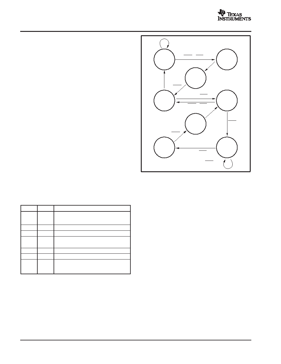
Figure 10 shows the state diagram of the DDC118. In all,
there are eight states. Table 5 provides a brief explanation
of each state.
Table 5. State Descriptions
STATE
MODE
DESCRIPTION
1
Ncont
Complete m/r/az of side A, then side B (if previous
state is state 4). Initial power-up state when CONV
is initially held HIGH.
2
Ncont
Prepare side A for integration.
3
Cont
Integrate on side A.
4
Cont
Integrate on side B; m/r/az on side A.
5
Cont
Integrate on side A; m/r/az on side B.
6
Cont
Integrate on side B.
7
Ncont
Prepare side B for integration.
8
Ncont
Complete m/r/az of side B, then side A (if previous
state is state 5). Initial power-up state when CONV
is initially held LOW.
Four signals are used to control progression around the
state diagram: CONV, mbsy, and their complements. The
state machine uses the level as opposed to the edges of
CONV to control the progression. mbsy is an internally-
generated signal not available to the user. It is active
whenever a measurement/reset/auto-zero (m/r/az) cycle
is in progress.
Int A/Meas B
Cont
5
CONV
× mbsy
CONV
× mbsy
CONV
× mbsy
CONV
× mbsy
CONV
× mbsy
CONV
× mbsy
CONV
Int B/Meas A
Cont
4
Ncont
1
Ncont
2
Int A
Cont
3
Ncont
8
Ncont
7
Int B
Cont
6
CONV
CONV|mbsy
Figure 10. Integrate/Measure State Diagram
During the cont mode, mbsy is not active when CONV
toggles. The non-integrating side is always ready to begin
integrating when the other side finishes its integration.
Consequently, monitoring the current status of CONV is all
that is needed to know the current state. Cont mode
operation corresponds to states 3-6. Two of the states, 3
and 6, only perform an integration (no m/r/az cycle).
mbsy becomes important when operating in the ncont
mode, states 1, 2, 7, and 8. Whenever CONV is toggled
while mbsy is active, the DDC118 will enter or remain in
either ncont state 1 (or 8). After mbsy goes inactive, state
2 (or 7) is entered. This state prepares the appropriate side
for integration. In the ncont states, the inputs to the
DDC118 are grounded.
One interesting observation from the state diagram is that
the integrations always alternate between sides A and B.
This relationship holds for any CONV pattern and is
independent of the mode. States 2 and 7 insure this
relationship during the ncont mode.
When power is first applied to the DDC118, the beginning
state is either 1 or 8, depending on the initial level of CONV.
For CONV held high at power-up, the beginning state is 1.
Conversely, for CONV held low at power-up, the beginning
state is 8. In general, there is a symmetry in the state
diagram between states 1-8, 2-7, 3-6, and 4-5. Inverting
CONV results in the states progressing through their
symmetrical match.
相关PDF资料 |
PDF描述 |
|---|---|
| DPB25F0/25F | 50 CONTACT(S), FEMALE-FEMALE, D SUBMINIATURE CONNECTOR, SOLDER |
| DPB25M/25M0 | 50 CONTACT(S), MALE-MALE, D SUBMINIATURE CONNECTOR, SOLDER |
| DPB25M/25M | 50 CONTACT(S), MALE-MALE, D SUBMINIATURE CONNECTOR, SOLDER |
| DPB25M0/25M0 | 50 CONTACT(S), MALE-MALE, D SUBMINIATURE CONNECTOR, SOLDER |
| DPB25M0/25M | 50 CONTACT(S), MALE-MALE, D SUBMINIATURE CONNECTOR, SOLDER |
相关代理商/技术参数 |
参数描述 |
|---|---|
| DDC118IRTCT | 制造商:Texas Instruments 功能描述:IC ADC 20BIT OCTAL 48-VQFN |
| DDC118IRTCT | 制造商:Texas Instruments 功能描述:A/D CONVERTER (A-D) IC ((NW)) |
| DDC118IRTCTG4 | 功能描述:模数转换器 - ADC Octal Current-Input 20-Bit RoHS:否 制造商:Texas Instruments 通道数量:2 结构:Sigma-Delta 转换速率:125 SPs to 8 KSPs 分辨率:24 bit 输入类型:Differential 信噪比:107 dB 接口类型:SPI 工作电源电压:1.7 V to 3.6 V, 2.7 V to 5.25 V 最大工作温度:+ 85 C 安装风格:SMD/SMT 封装 / 箱体:VQFN-32 |
| DDC11XEVM-PDK | 功能描述:数据转换 IC 开发工具 DDC11xEVM-PDK Eval Mod RoHS:否 制造商:Texas Instruments 产品:Demonstration Kits 类型:ADC 工具用于评估:ADS130E08 接口类型:SPI 工作电源电压:- 6 V to + 6 V |
| DDC122LH | 制造商:DIODES 制造商全称:Diodes Incorporated 功能描述:NPN PRE-BIASED SMALL SIGNAL SOT-563 DUAL SURFACE MOUNT TRANSISTOR |
发布紧急采购,3分钟左右您将得到回复。