- 您现在的位置:买卖IC网 > PDF目录1915 > DS31256+ (Maxim Integrated Products)IC CTRLR HDLC 256-CHANNEL 256BGA PDF资料下载
参数资料
| 型号: | DS31256+ |
| 厂商: | Maxim Integrated Products |
| 文件页数: | 156/183页 |
| 文件大小: | 0K |
| 描述: | IC CTRLR HDLC 256-CHANNEL 256BGA |
| 产品培训模块: | Lead (SnPb) Finish for COTS Obsolescence Mitigation Program |
| 标准包装: | 40 |
| 控制器类型: | HDLC 控制器 |
| 接口: | 串行 |
| 电源电压: | 3 V ~ 3.6 V |
| 电流 - 电源: | 500mA |
| 工作温度: | 0°C ~ 70°C |
| 安装类型: | 表面贴装 |
| 封装/外壳: | 256-BBGA |
| 供应商设备封装: | 256-BGA(27x27) |
| 包装: | 管件 |
第1页第2页第3页第4页第5页第6页第7页第8页第9页第10页第11页第12页第13页第14页第15页第16页第17页第18页第19页第20页第21页第22页第23页第24页第25页第26页第27页第28页第29页第30页第31页第32页第33页第34页第35页第36页第37页第38页第39页第40页第41页第42页第43页第44页第45页第46页第47页第48页第49页第50页第51页第52页第53页第54页第55页第56页第57页第58页第59页第60页第61页第62页第63页第64页第65页第66页第67页第68页第69页第70页第71页第72页第73页第74页第75页第76页第77页第78页第79页第80页第81页第82页第83页第84页第85页第86页第87页第88页第89页第90页第91页第92页第93页第94页第95页第96页第97页第98页第99页第100页第101页第102页第103页第104页第105页第106页第107页第108页第109页第110页第111页第112页第113页第114页第115页第116页第117页第118页第119页第120页第121页第122页第123页第124页第125页第126页第127页第128页第129页第130页第131页第132页第133页第134页第135页第136页第137页第138页第139页第140页第141页第142页第143页第144页第145页第146页第147页第148页第149页第150页第151页第152页第153页第154页第155页当前第156页第157页第158页第159页第160页第161页第162页第163页第164页第165页第166页第167页第168页第169页第170页第171页第172页第173页第174页第175页第176页第177页第178页第179页第180页第181页第182页第183页
DS31256 256-Channel, High-Throughput HDLC Controller
74 of 183
8. FIFO
8.1 General Description and Example
The DS31256 contains one 16kB FIFO for the receive path and another 16kB FIFO for the transmit path.
Both of these FIFOs are organized into blocks. Since a block is defined as 4 dwords (16 Bytes), each
FIFO is made up of 1024 blocks. Figure 8-1 shows an FIFO example.
The FIFO contains a state machine that is constantly polling the 16 ports to determine if any data is ready
for transfer to/from the FIFO from/to the HDLC engines. The 16 ports are priority decoded with port 0
getting the highest priority and port 15 getting the lowest priority. Therefore, all the enabled HDLC
channels on the lower numbered ports are serviced before the higher numbered ports. As long as the
maximum throughput rate of 132Mbps is not exceeded, the DS31256 ensures there is enough bandwidth
in this transfer to prevent any data loss between the HDLC engines and the FIFO.
The FIFO also controls which HDLC channel the DMA should service to read data out of the FIFO on
the receive side and to write data into the FIFO on the transmit side. Which channel gets the highest
priority from the FIFO is configurable through some control bits in the master configuration register
(Section 5.2). There are two control bits for the receive side (RFPC0 and RFPC1) and two control bits
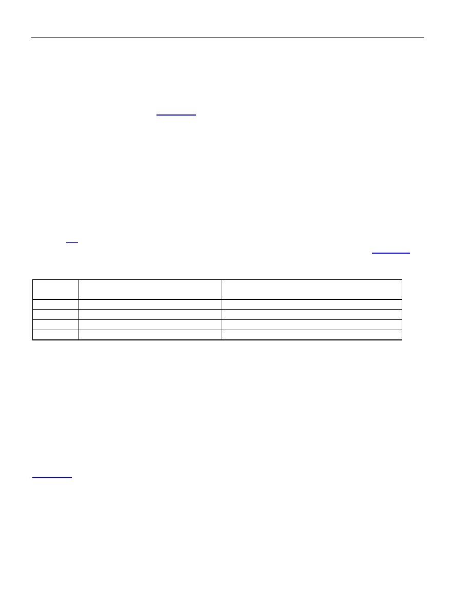
for the transmit side (TFPC0 and TFPC1) that determine the priority algorithm as shown in Table 8-A.
Table 8-A. FIFO Priority Algorithm Select
OPTION
HDLC CHANNELS THAT ARE
PRIORITY DECODED
HDLC CHANNELS THAT ARE SERVICED
ROUND ROBIN
1
None
1 to 256
2
1 to 3
4 to 256
3
16 to 1
17 to 256
4
64 to 1
65 to 256
To maintain maximum flexibility for channel reconfiguration, each block within the FIFO can be
assigned to any of the 256 HDLC channels. Also, blocks are link-listed together to form a chain whereby
each block points to the next block in the chain. The minimum size of the link-listed chain is 4 blocks
(64 Bytes) and the maximum is the full size of the FIFO, which is 1024 blocks.
To assign a set of blocks to a particular HDLC channel, the host must configure the starting block pointer
and the block pointer RAM. The starting block pointer assigns a particular HDLC channel to a set of
link-listed blocks by pointing to one of the blocks within the chain (it does not matter which block in the
chain is pointed to). The block pointer RAM must be configured for each block that is being used within
the FIFO. The block pointer RAM indicates the next block in the link-listed chain.
Figure 8-1 shows an example of how to configure the starting block pointer and the block pointer RAM.
In this example, only three HDLC channels are being used (channels 2, 6, and 16). The device knows
that channel 2 has been assigned to the eight link-listed blocks of 112, 118, 119, 120, 121, 122, 125, and
126 because a block pointer of 125 has been programmed into the channel 2 position of the starting
block pointer. The block pointer RAM tells the device how to link the eight blocks together to form a
circular chain.
The host must set the watermarks for the receive and transmit paths. The receive path has a high
watermark and the transmit path has a low watermark.
相关PDF资料 |
PDF描述 |
|---|---|
| DS3141+ | IC FRAMER DS3/E3 SNGL 144CSBGA |
| DS31412N | IC 12CH DS3/3 FRAMER 349-BGA |
| DS3150TN | IC LIU T3/E3/STS-1 IND 48-TQFP |
| DS3154N+ | IC LIU DS3/E3/STS-1 QD 144CSBGA |
| DS3164+ | IC ATM/PACKET PHY QUAD 400-BGA |
相关代理商/技术参数 |
参数描述 |
|---|---|
| DS31256+ | 功能描述:输入/输出控制器接口集成电路 256Ch High Thruput HDLC Cntlr RoHS:否 制造商:Silicon Labs 产品: 输入/输出端数量: 工作电源电压: 最大工作温度:+ 85 C 最小工作温度:- 40 C 安装风格:SMD/SMT 封装 / 箱体:QFN-64 封装:Tray |
| DS31256B | 功能描述:输入/输出控制器接口集成电路 256Ch High Thruput HDLC Cntlr RoHS:否 制造商:Silicon Labs 产品: 输入/输出端数量: 工作电源电压: 最大工作温度:+ 85 C 最小工作温度:- 40 C 安装风格:SMD/SMT 封装 / 箱体:QFN-64 封装:Tray |
| DS31256DK | 功能描述:网络开发工具 RoHS:否 制造商:Rabbit Semiconductor 产品:Development Kits 类型:Ethernet to Wi-Fi Bridges 工具用于评估:RCM6600W 数据速率:20 Mbps, 40 Mbps 接口类型:802.11 b/g, Ethernet 工作电源电压:3.3 V |
| DS31256-W+ | 制造商:Maxim Integrated Products 功能描述:ENVOY 256 CHANNEL HDLC - WAIVER - Rail/Tube |
| DS312BNC | 制造商:未知厂家 制造商全称:未知厂家 功能描述:Industrial Control IC |
发布紧急采购,3分钟左右您将得到回复。