参数资料
| 型号: | ISL6308CRZ |
| 厂商: | Intersil |
| 文件页数: | 9/28页 |
| 文件大小: | 0K |
| 描述: | IC CTRLR PWM 3PHASE BUCK 40-QFN |
| 标准包装: | 500 |
| 应用: | 控制器,DDR |
| 输入电压: | 5 V ~ 12 V |
| 输出数: | 1 |
| 输出电压: | 0.6 V ~ 2.3 V |
| 工作温度: | 0°C ~ 70°C |
| 安装类型: | 表面贴装 |
| 封装/外壳: | 40-VFQFN 裸露焊盘 |
| 供应商设备封装: | 40-QFN(6x6) |
| 包装: | 管件 |
第1页第2页第3页第4页第5页第6页第7页第8页当前第9页第10页第11页第12页第13页第14页第15页第16页第17页第18页第19页第20页第21页第22页第23页第24页第25页第26页第27页第28页
�� �
�
�ISL6308�
�PHASE1,� PHASE2,� and� PHASE3� (Pins� 29,� 28,� 22)�
�Connect� these� pins� to� the� sources� of� the� upper� MOSFETs.�
�These� pins� are� the� return� path� for� the� upper� MOSFETs’�
�drives.�
�LGATE1,� LGATE2,� and� LGATE3� (Pins� 34,� 23,� 17)�
�These� pins� are� used� to� control� the� lower� MOSFETs� and� are�
�monitored� for� shoot-through� prevention� purposes.� Connect�
�these� pins� to� the� lower� MOSFETs’� gates.� Do� not� use� external�
�series� gate� resistors� as� this� might� lead� to� shoot-through.�
�PGOOD� (Pin� 35)�
�PGOOD� is� used� as� an� indication� of� the� end� of� soft-start.� It� is�
�an� open-drain� logic� output� that� is� low� impedance� until� the�
�soft-start� is� completed� and� VOUT� is� equal� to� the� VID� setting.�
�Once� in� normal� operation,� PGOOD� indicates� whether� the�
�output� voltage� is� within� specified� overvoltage� and�
�undervoltage� limits.� If� the� output� voltage� exceeds� these� limits�
�or� a� reset� event� occurs� (such� as� an� overcurrent� event),�
�PGOOD� becomes� high� impedance� again.� The� potential� at�
�this� pin� should� not� exceed� that� of� the� potential� at� VCC� pin� by�
�more� than� a� typical� forward� diode� drop� at� any� time.�
�OVP� (Pin� 38)�
�Overvoltage� protection� pin.� This� pin� pulls� to� VCC� when� an�
�overvoltage� condition� is� detected.� Connect� this� pin� to� the�
�gate� of� an� SCR� or� MOSFET� tied� across� V� IN� and� ground� to�
�prevent� damage� to� a� load� device.�
�can� use� less� per-channel� inductance� and� lower� total� output�
�capacitance� for� any� performance� specification.�
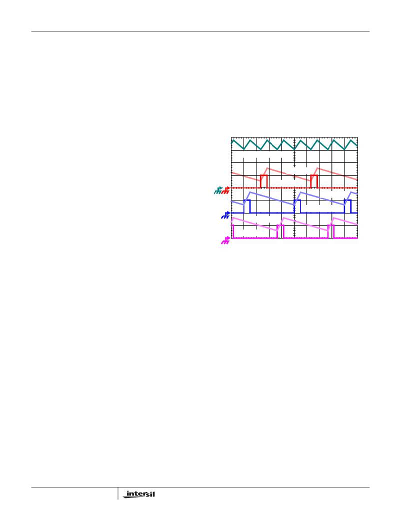
�Figure� 1� illustrates� the� multiplicative� effect� on� output� ripple�
�frequency.� The� three� channel� currents� (I� L1� ,� I� L2� ,� and� I� L3� )�
�combine� to� form� the� AC� ripple� current� and� the� DC� load�
�current.� The� ripple� component� has� three� times� the� ripple�
�frequency� of� each� individual� channel� current.� Each� PWM�
�pulse� is� terminated� one� third� of� a� cycle� after� the� PWM� pulse� of�
�the� previous� phase.� The� peak-to-peak� current� for� each� phase�
�is� about� 7A,� and� the� DC� components� of� the� inductor� currents�
�combine� to� feed� the� load.�
�I� L1� +� I� L2� +� I� L3� ,� 7A/DIV�
�I� L3� ,� 7A/DIV�
�PWM3,� 5V/DIV�
�I� L2� , 7A/DIV�
�PWM2,� 5V/DIV�
�I� L1� ,� 7A/DIV�
�PWM1,� 5V/DIV�
�FIGURE� 1.� PWM� AND� INDUCTOR-CURRENT� WAVEFORMS�
�FOR� 3-PHASE� CONVERTER�
�Operation�
�Multi-Phase� Power� Conversion�
�Modern� low� voltage� DC/DC� converter� load� current� profiles�
�To� understand� the� reduction� of� ripple� current� amplitude� in� the�
�multi-phase� circuit,� examine� Equation� 1,� which� represents�
�an� individual� channel� peak-to-peak� inductor� current.�
�(� V� IN� –� V� OUT� )� ?� V� OUT�
�L� ?� F� SW� ?� V� IN�
�have� changed� to� the� point� that� the� advantages� of� multi-phase�
�power� conversion� are� impossible� to� ignore.� The� technical�
�challenges� associated� with� producing� a� single-phase�
�I� PP� =� ----------------------------------------------------------�
�(EQ.� 1)�
�converter� that� is� both� cost-effective� and� thermally� viable� have�
�forced� a� change� to� the� cost-saving� approach� of� multi-phase.�
�The� ISL6308� controller� helps� simplify� implementation� by�
�integrating� vital� functions� and� requiring� minimal� output�
�components.� The� “Block� Diagram”� on� page� 3� provides� a� top�
�level� view� of� multi-phase� power� conversion� using� the� ISL6308�
�controller.�
�Interleaving�
�The� switching� of� each� channel� in� a� multi-phase� converter� is�
�timed� to� be� symmetrically� out-of-phase� with� each� of� the�
�other� channels.� In� a� 3-phase� converter,� each� channel�
�switches� one� third� cycle� after� the� previous� channel� and� one�
�third� cycle� before� the� following� channel.� As� a� result,� the�
�three-phase� converter� has� a� combined� ripple� frequency�
�three� times� greater� than� the� ripple� frequency� of� any� one�
�In� Equation� 1,� V� IN� and� V� OUT� are� the� input� and� output�
�voltages� respectively,� L� is� the� single-channel� inductor� value,�
�and� F� SW� is� the� switching� frequency.�
�The� output� capacitors� conduct� the� ripple� component� of� the�
�inductor� current.� In� the� case� of� multi-phase� converters,� the�
�capacitor� current� is� the� sum� of� the� ripple� currents� from� each�
�of� the� individual� channels.� Compare� Equation� 1� to� the�
�expression� for� the� peak-to-peak� current� after� the� summation�
�of� N� symmetrically� phase-shifted� inductor� currents� in�
�Equation� 2.� Peak-to-peak� ripple� current� decreases� by� an�
�amount� proportional� to� the� number� of� channels.� Output�
�voltage� ripple� is� a� function� of� capacitance,� capacitor�
�equivalent� series� resistance� (ESR),� and� inductor� ripple�
�current.� Reducing� the� inductor� ripple� current� allows� the�
�designer� to� use� fewer� or� less� costly� output� capacitors.�
�L� ?� F� SW� ?� V�
�phase.� In� addition,� the� peak-to-peak� amplitude� of� the�
�combined� inductor� currents� is� reduced� in� proportion� to� the�
�number� of� phases� (Equations� 1� and� 2).� Increased� ripple�
�frequency� and� lower� ripple� amplitude� mean� that� the� designer�
�9�
�(� V� IN� –� N� ?� V� OUT� )� ?� V� OUT�
�I� C� ,� PP� =� --------------------------------------------------------------------�
�IN�
�(EQ.� 2)�
�FN9208.4�
�September� 30,� 2008�
�相关PDF资料 |
PDF描述 |
|---|---|
| ACM18DRSN-S288 | CONN EDGECARD EXTEND 36POS 0.156 |
| RCM22DTAD-S189 | CONN EDGECARD 44POS R/A .156 SLD |
| MAX8860EUA28+ | IC REG LDO 2.82V/ADJ .3A 8-UMAX |
| 2512-562K | INDUCTOR POWER 5.6UH MOLDED SMD |
| ACM18DRSH-S288 | CONN EDGECARD EXTEND 36POS 0.156 |
相关代理商/技术参数 |
参数描述 |
|---|---|
| ISL6308CRZR5374 | 制造商:Intersil Corporation 功能描述:ISL6308CRZ W/ 24HR BURN-IN - Rail/Tube 制造商:Intersil Corporation 功能描述:IC CTRLR PWM 3PHASE BUCK 40-QFN 制造商:Intersil 功能描述:ISL6308CRZ W/24HRU RN-IN |
| ISL6308CRZ-T | 功能描述:电压模式 PWM 控制器 DAC-LESS MULTI-PHS PWM CNTRLR W/3-DRVRS RoHS:否 制造商:Texas Instruments 输出端数量:1 拓扑结构:Buck 输出电压:34 V 输出电流: 开关频率: 工作电源电压:4.5 V to 5.5 V 电源电流:600 uA 最大工作温度:+ 125 C 最小工作温度:- 40 C 封装 / 箱体:WSON-8 封装:Reel |
| ISL6308CRZ-TR5374 | 制造商:Intersil Corporation 功能描述:ISL6308CRZ W/ 24HR BURN-IN - Tape and Reel 制造商:Intersil Corporation 功能描述:IC CTRLR PWM 3PHASE BUCK 40-QFN 制造商:Intersil 功能描述:ISL6308CRZ W/24HRU RN-IN |
| ISL6308CRZ-TR5453 | 制造商:Intersil Corporation 功能描述:STD. ISL6308CRZ-T W/GOLD BOND WIRE ONLY - Tape and Reel |
| ISL6308EVAL1Z | 制造商:Intersil Corporation 功能描述:ISL6308 EVALUATION BOARD 1 - ROHS COMPLIANT - QFN - Bulk |
发布紧急采购,3分钟左右您将得到回复。