- 您现在的位置:买卖IC网 > PDF目录80565 > M68LC302CPU20VCT (FREESCALE SEMICONDUCTOR INC) 4 CHANNEL(S), 10M bps, LOCAL AREA NETWORK CONTROLLER, PQFP100 PDF资料下载
参数资料
| 型号: | M68LC302CPU20VCT |
| 厂商: | FREESCALE SEMICONDUCTOR INC |
| 元件分类: | 微控制器/微处理器 |
| 英文描述: | 4 CHANNEL(S), 10M bps, LOCAL AREA NETWORK CONTROLLER, PQFP100 |
| 封装: | 14 X 14 MM, 1.40 MM HEIGHT, 0.50 MM PITCH, PLASITC, LQFP-100 |
| 文件页数: | 91/128页 |
| 文件大小: | 641K |
| 代理商: | M68LC302CPU20VCT |
第1页第2页第3页第4页第5页第6页第7页第8页第9页第10页第11页第12页第13页第14页第15页第16页第17页第18页第19页第20页第21页第22页第23页第24页第25页第26页第27页第28页第29页第30页第31页第32页第33页第34页第35页第36页第37页第38页第39页第40页第41页第42页第43页第44页第45页第46页第47页第48页第49页第50页第51页第52页第53页第54页第55页第56页第57页第58页第59页第60页第61页第62页第63页第64页第65页第66页第67页第68页第69页第70页第71页第72页第73页第74页第75页第76页第77页第78页第79页第80页第81页第82页第83页第84页第85页第86页第87页第88页第89页第90页当前第91页第92页第93页第94页第95页第96页第97页第98页第99页第100页第101页第102页第103页第104页第105页第106页第107页第108页第109页第110页第111页第112页第113页第114页第115页第116页第117页第118页第119页第120页第121页第122页第123页第124页第125页第126页第127页第128页
ETHERNET Controller
4-26
MC68EN302 REFERENCE MANUAL
MOTOROLA
Because each entry in the perfect-match table is 48 bits, but no more than 16 bits can be
written at a time; byte 5(or the word consisting of bytes 4 and 5 of a perfect-match entry)
must be written last. This prevents an address compare from occurring on partially-written
entries. When the first byte (or word) of an entry is written, that entry is temporarily disabled
until byte 5 (or a word consisting of bytes 4 and 5) is written.
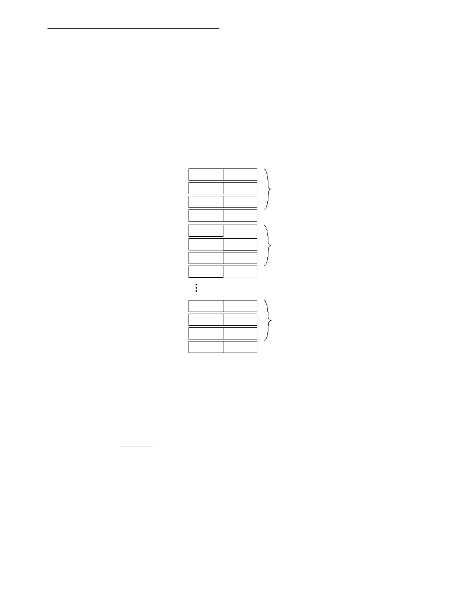
The Address Recognition memory map for perfect match mode is shown in Figure 4-5. The
least significant bit of byte 0 (bit 8 of word MOBA + $A00, +$A08,...) corresponds to the I/G
address bit - this is the first bit received off the wire. The order of the bits received starts with
Byte 0-bit0 and continues through Byte0-bit7. The next byte is received as Byte1-bit0,
Byte1-bit1,...Byte1-bit7 up through byte 5.
Figure 4-5. AR Memory Map - Perfect Match Mode
When HASH_EN is set, the last two entries in the table are used for the logical address filter
mask bits. Hash index 0 is located in the least significant bit of byte 7 in the hash table
(MOBA + BFB). Hash index 63 is bit 7 of byte 0 (MOBA + BF0) in the hash table. When
writing logical address filter mask bits there is no restriction on the ordering of the writes.
When HASH_EN is set, the memory map is changed as shown in Figure 4-6. When
HASH_EN is set, locations MOBA + BF4, + BF6 AND MOBA + BFC, +BFE should not be
read or written to (DTACK will not be returned).
MOBA +$ A00
MOBA + $A02
MOBA + $A04
MOBA + $A06
BYTE 5
BYTE0
UNUSED
FIRST ENTRY
MOBA + $A08
MOBA + $A0A
MOBA + $A0C
MOBA + $A0E
BYTE 5
BYTE 0
UNUSED
SECOND ENTRY
MOBA + $BF8
MOBA + $BFA
MOBA + $BFC
MOBA + $BFE
BYTE 5
BYTE 0
UNUSED
LAST ENTRY
BYTE 1
BYTE 2
BYTE 3
BYTE 4
相关PDF资料 |
PDF描述 |
|---|---|
| MC68030FE25C | 32-BIT, 25 MHz, MICROPROCESSOR, CQFP132 |
| MC68302CPV16VC | 4 CHANNEL(S), 10M bps, LOCAL AREA NETWORK CONTROLLER, PQFP144 |
| MC68331CFC16B1 | 32-BIT, 16 MHz, MICROCONTROLLER, PQFP132 |
| MC68882CRC16A | 32-BIT, MATH COPROCESSOR, CPGA68 |
| MC68HC11E1VFN3 | 8-BIT, 3 MHz, MICROCONTROLLER, PQCC52 |
相关代理商/技术参数 |
参数描述 |
|---|---|
| M68LGL061X | 制造商:Panasonic Industrial Company 功能描述:SUB ONLY CRT |
| M68LGL061XA | 制造商:Panasonic Industrial Company 功能描述:CRT OR M68LGL061X |
| M68LNK161X | 制造商:Panasonic Industrial Company 功能描述:CRT |
| M68LUQ085X | 制造商:Panasonic Industrial Company 功能描述:CRT |
| M68LZP195X | 制造商:Panasonic Industrial Company 功能描述:CRT |
发布紧急采购,3分钟左右您将得到回复。