- 您现在的位置:买卖IC网 > PDF目录80585 > MB9AF312NPMC 32-BIT, FLASH, 40 MHz, RISC MICROCONTROLLER, PQFP100 PDF资料下载
参数资料
| 型号: | MB9AF312NPMC |
| 元件分类: | 微控制器/微处理器 |
| 英文描述: | 32-BIT, FLASH, 40 MHz, RISC MICROCONTROLLER, PQFP100 |
| 封装: | 0.50 MM PITCH, PLASTIC, LQFP-100 |
| 文件页数: | 109/114页 |
| 文件大小: | 1357K |
| 代理商: | MB9AF312NPMC |
第1页第2页第3页第4页第5页第6页第7页第8页第9页第10页第11页第12页第13页第14页第15页第16页第17页第18页第19页第20页第21页第22页第23页第24页第25页第26页第27页第28页第29页第30页第31页第32页第33页第34页第35页第36页第37页第38页第39页第40页第41页第42页第43页第44页第45页第46页第47页第48页第49页第50页第51页第52页第53页第54页第55页第56页第57页第58页第59页第60页第61页第62页第63页第64页第65页第66页第67页第68页第69页第70页第71页第72页第73页第74页第75页第76页第77页第78页第79页第80页第81页第82页第83页第84页第85页第86页第87页第88页第89页第90页第91页第92页第93页第94页第95页第96页第97页第98页第99页第100页第101页第102页第103页第104页第105页第106页第107页第108页当前第109页第110页第111页第112页第113页第114页
ATmega48PA/88PA/168PA [DATASHEET]
9223F–AVR–04/14
94
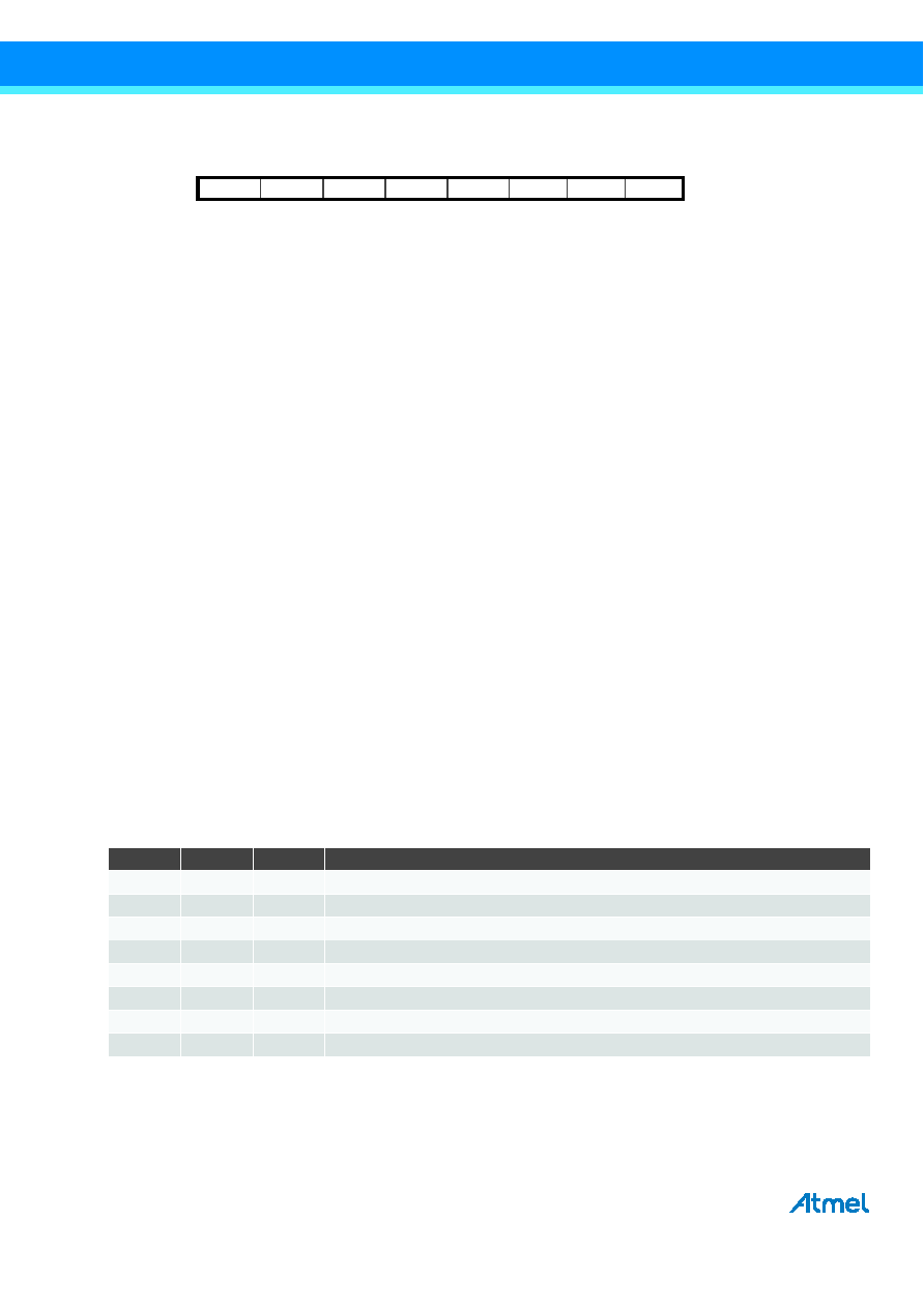
15.9.2 TCCR0B – Timer/Counter Control Register B
Bit 7 – FOC0A: Force Output Compare A
The FOC0A bit is only active when the WGM bits specify a non-PWM mode.
However, for ensuring compatibility with future devices, this bit must be set to zero when TCCR0B is written when operating
in PWM mode. When writing a logical one to the FOC0A bit, an immediate compare match is forced on the waveform
generation unit. The OC0A output is changed according to its COM0A1:0 bits setting. Note that the FOC0A bit is
implemented as a strobe. Therefore it is the value present in the COM0A1:0 bits that determines the effect of the forced
compare.
A FOC0A strobe will not generate any interrupt, nor will it clear the timer in CTC mode using OCR0A as TOP.
The FOC0A bit is always read as zero.
Bit 6 – FOC0B: Force Output Compare B
The FOC0B bit is only active when the WGM bits specify a non-PWM mode.
However, for ensuring compatibility with future devices, this bit must be set to zero when TCCR0B is written when operating
in PWM mode. When writing a logical one to the FOC0B bit, an immediate compare match is forced on the waveform
generation unit. The OC0B output is changed according to its COM0B1:0 bits setting. Note that the FOC0B bit is
implemented as a strobe. Therefore it is the value present in the COM0B1:0 bits that determines the effect of the forced
compare.
A FOC0B strobe will not generate any interrupt, nor will it clear the timer in CTC mode using OCR0B as TOP.
The FOC0B bit is always read as zero.
Bits 5:4 – Reserved
These bits are reserved bits in the Atmel ATmega48PA/88PA/168PA and will always read as zero.
Bit 3 – WGM02: Waveform Generation Mode
See the description in the Section 15.9.1 “TCCR0A – Timer/Counter Control Register A” on page 91.
Bits 2:0 – CS02:0: Clock Select
The three clock select bits select the clock source to be used by the Timer/Counter.
If external pin modes are used for the Timer/Counter0, transitions on the T0 pin will clock the counter even if the pin is
configured as an output. This feature allows software control of the counting.
Bit
7
6
5
4
3
2
1
0
FOC0A
FOC0B
–
WGM02
CS02
CS01
CS00
TCCR0B
Read/Write
W
R
R/W
Initial Value
0
Table 15-9. Clock Select Bit Description
CS02
CS01
CS00
Description
0
No clock source (timer/ccounter stopped)
0
1
clkI/O/(no prescaling)
0
1
0
clkI/O/8 (from prescaler)
0
1
clkI/O/64 (from prescaler)
1
0
clkI/O/256 (from prescaler)
1
0
1
clkI/O/1024 (from prescaler)
1
0
External clock source on T0 pin. Clock on falling edge.
1
External clock source on T0 pin. Clock on rising edge.
相关PDF资料 |
PDF描述 |
|---|---|
| MB9AF315NPF | 32-BIT, FLASH, 40 MHz, RISC MICROCONTROLLER, PQFP100 |
| MSM65P514-JS | 8-BIT, OTPROM, 12 MHz, MICROCONTROLLER, PQCC68 |
| MSM67P620-JS | 16-BIT, OTPROM, 10 MHz, MICROCONTROLLER, PQCC68 |
| MSM80C154-RS | 8-BIT, 12 MHz, MICROCONTROLLER, PDIP40 |
| MSM83C154-RS | 8-BIT, MROM, 12 MHz, MICROCONTROLLER, PDIP40 |
相关代理商/技术参数 |
参数描述 |
|---|---|
| MB9AF314LAPMC1-G-JNE2 | 制造商:FUJITSU 功能描述: |
| MB9AF314LAPMC-G-JNE2 | 制造商:Fujitsu 功能描述:Bulk |
| MB9AF314LAQN-G-AVE2 | 功能描述:ARM? Cortex?-M3 FM3 MB9A310A Microcontroller IC 32-Bit 40MHz 256KB (256K x 8) FLASH 64-QFN Exposed Pad (9x9) 制造商:cypress semiconductor corp 系列:FM3 MB9A310A 包装:托盘 零件状态:有效 核心处理器:ARM? Cortex?-M3 核心尺寸:32-位 速度:40MHz 连接性:CSIO,I2C,LIN,UART/USART,USB 外设:DMA,LVD,POR,PWM,WDT I/O 数:51 程序存储容量:256KB(256K x 8) 程序存储器类型:闪存 EEPROM 容量:- RAM 容量:32K x 8 电压 - 电源(Vcc/Vdd):2.7 V ~ 5.5 V 数据转换器:A/D 9x12b 振荡器类型:内部 工作温度:-40°C ~ 105°C(TA) 封装/外壳:64-VFQFN 裸露焊盘 供应商器件封装:64-QFN 裸露焊盘(9x9) 标准包装:260 |
| MB9AF314LPMC1-ESE1 | 制造商:FUJITSU 功能描述: |
| MB9AF314LPMC1-GE1 | 制造商:FUJITSU 功能描述: |
发布紧急采购,3分钟左右您将得到回复。