- 您现在的位置:买卖IC网 > PDF目录80585 > MB9AF312NPMC 32-BIT, FLASH, 40 MHz, RISC MICROCONTROLLER, PQFP100 PDF资料下载
参数资料
| 型号: | MB9AF312NPMC |
| 元件分类: | 微控制器/微处理器 |
| 英文描述: | 32-BIT, FLASH, 40 MHz, RISC MICROCONTROLLER, PQFP100 |
| 封装: | 0.50 MM PITCH, PLASTIC, LQFP-100 |
| 文件页数: | 6/114页 |
| 文件大小: | 1357K |
| 代理商: | MB9AF312NPMC |
第1页第2页第3页第4页第5页当前第6页第7页第8页第9页第10页第11页第12页第13页第14页第15页第16页第17页第18页第19页第20页第21页第22页第23页第24页第25页第26页第27页第28页第29页第30页第31页第32页第33页第34页第35页第36页第37页第38页第39页第40页第41页第42页第43页第44页第45页第46页第47页第48页第49页第50页第51页第52页第53页第54页第55页第56页第57页第58页第59页第60页第61页第62页第63页第64页第65页第66页第67页第68页第69页第70页第71页第72页第73页第74页第75页第76页第77页第78页第79页第80页第81页第82页第83页第84页第85页第86页第87页第88页第89页第90页第91页第92页第93页第94页第95页第96页第97页第98页第99页第100页第101页第102页第103页第104页第105页第106页第107页第108页第109页第110页第111页第112页第113页第114页
103
ATmega48PA/88PA/168PA [DATASHEET]
9223F–AVR–04/14
16.5
Counter Unit
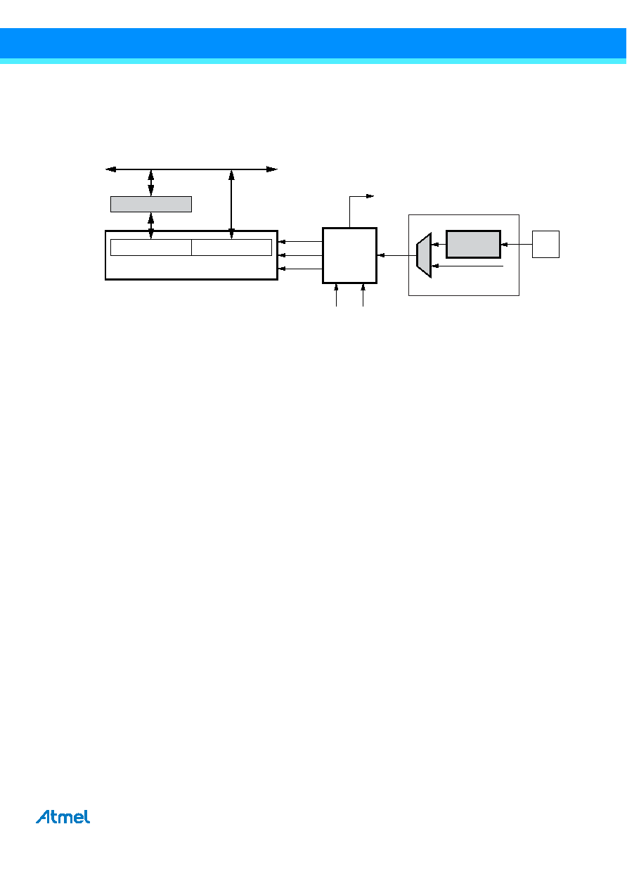
The main part of the 16-bit Timer/Counter is the programmable 16-bit bi-directional counter unit. Figure 16-2 shows a block
diagram of the counter and its surroundings.
Figure 16-2. Counter Unit Block Diagram
Signal description (internal signals):
Count
Increment or decrement TCNT1 by 1.
Direction
Select between increment and decrement.
Clear
Clear TCNT1 (set all bits to zero).
clkT1
Timer/Counter clock.
TOP
Signalize that TCNT1 has reached maximum value.
BOTTOM
Signalize that TCNT1 has reached minimum value (zero).
The 16-bit counter is mapped into two 8-bit I/O memory locations: Counter high (TCNT1H) containing the upper eight bits of
the counter, and counter low (TCNT1L) containing the lower eight bits. The TCNT1H register can only be indirectly accessed
by the CPU. When the CPU does an access to the TCNT1H I/O location, the CPU accesses the high byte temporary register
(TEMP). The temporary register is updated with the TCNT1H value when the TCNT1L is read, and TCNT1H is updated with
the temporary register value when TCNT1L is written. This allows the CPU to read or write the entire 16-bit counter value
within one clock cycle via the 8-bit data bus. It is important to notice that there are special cases of writing to the TCNT1
register when the counter is counting that will give unpredictable results. The special cases are described in the sections
where they are of importance.
Depending on the mode of operation used, the counter is cleared, incremented, or decremented at each timer clock (clkT1).
The clkT1 can be generated from an external or internal clock source, selected by the clock select bits (CS12:0). When no
clock source is selected (CS12:0 = 0) the timer is stopped. However, the TCNT1 value can be accessed by the CPU,
independent of whether clkT1 is present or not. A CPU write overrides (has priority over) all counter clear or count operations.
The counting sequence is determined by the setting of the waveform generation mode bits (WGM13:0) located in the
Timer/Counter control registers A and B (TCCR1A and TCCR1B). There are close connections between how the counter
behaves (counts) and how waveforms are generated on the output compare outputs OC1x. For more details about
advanced counting sequences and waveform generation, see Section 16.9 “Modes of Operation” on page 108.
The Timer/Counter overflow flag (TOV1) is set according to the mode of operation selected by the WGM13:0 bits. TOV1 can
be used for generating a CPU interrupt.
BOTTOM
TOP
TOVn
(Int. Req.)
DATA BUS (8-bit)
Control Logic
TCNTnH (8-bit)
TCNTnH (16-bit Counter)
TCNTnL (8-bit)
TEMP (8-bit)
clkTn
Clear
Count
Direction
Edge
Detector
(from Prescaler)
Clock Select
Tn
相关PDF资料 |
PDF描述 |
|---|---|
| MB9AF315NPF | 32-BIT, FLASH, 40 MHz, RISC MICROCONTROLLER, PQFP100 |
| MSM65P514-JS | 8-BIT, OTPROM, 12 MHz, MICROCONTROLLER, PQCC68 |
| MSM67P620-JS | 16-BIT, OTPROM, 10 MHz, MICROCONTROLLER, PQCC68 |
| MSM80C154-RS | 8-BIT, 12 MHz, MICROCONTROLLER, PDIP40 |
| MSM83C154-RS | 8-BIT, MROM, 12 MHz, MICROCONTROLLER, PDIP40 |
相关代理商/技术参数 |
参数描述 |
|---|---|
| MB9AF314LAPMC1-G-JNE2 | 制造商:FUJITSU 功能描述: |
| MB9AF314LAPMC-G-JNE2 | 制造商:Fujitsu 功能描述:Bulk |
| MB9AF314LAQN-G-AVE2 | 功能描述:ARM? Cortex?-M3 FM3 MB9A310A Microcontroller IC 32-Bit 40MHz 256KB (256K x 8) FLASH 64-QFN Exposed Pad (9x9) 制造商:cypress semiconductor corp 系列:FM3 MB9A310A 包装:托盘 零件状态:有效 核心处理器:ARM? Cortex?-M3 核心尺寸:32-位 速度:40MHz 连接性:CSIO,I2C,LIN,UART/USART,USB 外设:DMA,LVD,POR,PWM,WDT I/O 数:51 程序存储容量:256KB(256K x 8) 程序存储器类型:闪存 EEPROM 容量:- RAM 容量:32K x 8 电压 - 电源(Vcc/Vdd):2.7 V ~ 5.5 V 数据转换器:A/D 9x12b 振荡器类型:内部 工作温度:-40°C ~ 105°C(TA) 封装/外壳:64-VFQFN 裸露焊盘 供应商器件封装:64-QFN 裸露焊盘(9x9) 标准包装:260 |
| MB9AF314LPMC1-ESE1 | 制造商:FUJITSU 功能描述: |
| MB9AF314LPMC1-GE1 | 制造商:FUJITSU 功能描述: |
发布紧急采购,3分钟左右您将得到回复。