- 您现在的位置:买卖IC网 > PDF目录45211 > MC68307PU16 (MOTOROLA INC) 16-BIT, 16.67 MHz, MICROCONTROLLER, PQFP100 PDF资料下载
参数资料
| 型号: | MC68307PU16 |
| 厂商: | MOTOROLA INC |
| 元件分类: | 微控制器/微处理器 |
| 英文描述: | 16-BIT, 16.67 MHz, MICROCONTROLLER, PQFP100 |
| 封装: | TQFP-100 |
| 文件页数: | 241/264页 |
| 文件大小: | 949K |
| 代理商: | MC68307PU16 |
第1页第2页第3页第4页第5页第6页第7页第8页第9页第10页第11页第12页第13页第14页第15页第16页第17页第18页第19页第20页第21页第22页第23页第24页第25页第26页第27页第28页第29页第30页第31页第32页第33页第34页第35页第36页第37页第38页第39页第40页第41页第42页第43页第44页第45页第46页第47页第48页第49页第50页第51页第52页第53页第54页第55页第56页第57页第58页第59页第60页第61页第62页第63页第64页第65页第66页第67页第68页第69页第70页第71页第72页第73页第74页第75页第76页第77页第78页第79页第80页第81页第82页第83页第84页第85页第86页第87页第88页第89页第90页第91页第92页第93页第94页第95页第96页第97页第98页第99页第100页第101页第102页第103页第104页第105页第106页第107页第108页第109页第110页第111页第112页第113页第114页第115页第116页第117页第118页第119页第120页第121页第122页第123页第124页第125页第126页第127页第128页第129页第130页第131页第132页第133页第134页第135页第136页第137页第138页第139页第140页第141页第142页第143页第144页第145页第146页第147页第148页第149页第150页第151页第152页第153页第154页第155页第156页第157页第158页第159页第160页第161页第162页第163页第164页第165页第166页第167页第168页第169页第170页第171页第172页第173页第174页第175页第176页第177页第178页第179页第180页第181页第182页第183页第184页第185页第186页第187页第188页第189页第190页第191页第192页第193页第194页第195页第196页第197页第198页第199页第200页第201页第202页第203页第204页第205页第206页第207页第208页第209页第210页第211页第212页第213页第214页第215页第216页第217页第218页第219页第220页第221页第222页第223页第224页第225页第226页第227页第228页第229页第230页第231页第232页第233页第234页第235页第236页第237页第238页第239页第240页当前第241页第242页第243页第244页第245页第246页第247页第248页第249页第250页第251页第252页第253页第254页第255页第256页第257页第258页第259页第260页第261页第262页第263页第264页
EC000 Core Processor
4-2
MC68307 USER’S MANUAL
MOTOROLA
4.3 PROGRAMMING MODEL
The EC000 core executes instructions in one of two modes—user mode or supervisor
mode. The user mode provides the execution environment for the majority of application
programs. The supervisor mode, which allows some additional instructions and privileges,
is used by the operating system and other system software.
To provide upward compatibility of code written for a specific implementation of the EC000
core, the user programmer's model, illustrated in Figure 4-1, is common to all implementa-
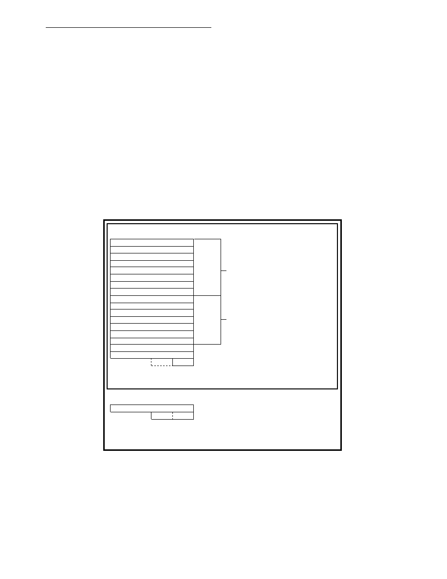
tions. In the user programmer's model, the EC000 core offers 16, 32-bit, general-purpose
registers (D7–D0, A7–A0), a 32-bit program counter, and an 8-bit condition code register.
The first eight registers (D7–D0) are used as data registers for byte (8-bit), word (16-bit), and
long-word (32-bit) operations. The second set of seven registers (A6–A0) and the user stack
pointer (USP) can be used as software stack pointers and base address registers. In addi-
tion, the address registers can be used for word and long-word operations. All of the 16 reg-
isters can be used as index registers. The supervisor programmer's model consists of
supplementary registers used in the supervisor mode.
The status register, illustrated in Figure 4-2, contains the interrupt mask (eight levels avail-
able) and the following condition codes: overflow (V), zero (Z), negative (N), carry (C), and
extend (X). Additional status bits indicate that the processor is in the trace (T) mode and/or
in the supervisor (S) state.
Figure 4-1. Programming Model
SUPERVISOR PROGRAMMING MODEL
USER PROGRAMMING MODEL
CCR
PC
A7/USP
A6
A5
A4
A3
A2
A1
A0
D7
D6
D5
D4
D3
D2
D1
D0
31
0
31
0
SSP
SR
(CCR)
PROGRAM COUNTER
CONDITION CODE REGISTER
SUPERVISOR STACK POINTER
STATUS REGISTER (CCR IS ALSO SHOWN IN
THE USER PROGRAMMING MODEL)
USER STACK POINTER
DATA REGISTERS
ADDRESS REGISTERS
相关PDF资料 |
PDF描述 |
|---|---|
| MC68307PU16V | 16-BIT, 16.67 MHz, MICROCONTROLLER, PQFP100 |
| MC68307FG16 | 16-BIT, 16.67 MHz, MICROCONTROLLER, PQFP100 |
| MC68322FT16 | 16-BIT, 16.667 MHz, RISC PROCESSOR, PQFP160 |
| MC68331CFC20B1 | 32-BIT, 20 MHz, MICROCONTROLLER, PQFP132 |
| MC68331CPV20B1 | 32-BIT, 20 MHz, MICROCONTROLLER, PQFP144 |
相关代理商/技术参数 |
参数描述 |
|---|---|
| MC68307UM | 制造商:MOTOROLA 制造商全称:Motorola, Inc 功能描述:Technical Summary Integrated Multiple-Bus Processor |
| MC68307V | 制造商:MOTOROLA 制造商全称:Motorola, Inc 功能描述:Technical Summary Integrated Multiple-Bus Processor |
| MC68322 | 制造商:MOTOROLA 制造商全称:Motorola, Inc 功能描述:Integrated Printer Processor |
| MC68322AD | 制造商:MOTOROLA 制造商全称:Motorola, Inc 功能描述:Integrated Printer Processor |
| MC68322FT20 | 制造商:Rochester Electronics LLC 功能描述:- Bulk |
发布紧急采购,3分钟左右您将得到回复。