- 您现在的位置:买卖IC网 > PDF目录385639 > MT28F200B5 (Micron Technology, Inc.) FLASH MEMORY PDF资料下载
参数资料
| 型号: | MT28F200B5 |
| 厂商: | Micron Technology, Inc. |
| 英文描述: | FLASH MEMORY |
| 中文描述: | 闪存 |
| 文件页数: | 10/31页 |
| 文件大小: | 558K |
| 代理商: | MT28F200B5 |
第1页第2页第3页第4页第5页第6页第7页第8页第9页当前第10页第11页第12页第13页第14页第15页第16页第17页第18页第19页第20页第21页第22页第23页第24页第25页第26页第27页第28页第29页第30页第31页
10
2Mb Smart 3 Boot Block Flash Memory
F48.p65 – Rev. 1/00
Micron Technology, Inc., reserves the right to change products or specifications without notice.
2000, Micron Technology, Inc.
2Mb
SMART 3 BOOT BLOCK FLASH MEMORY
INPUT OPERATIONS
The DQ pins are used either to input data to the
array or to input a command to the CEL. A command
input issues an 8-bit command to the CEL to control the
mode of operation of the device. A WRITE is used to
input data to the memory array. The following section
describes both types of inputs. More information de-
scribing how to use the two types of inputs to write or
erase the device is provided in the Command Execution
section.
COMMANDS
To perform a command input, OE# must be HIGH,
and CE# and WE# must be LOW. Addresses are “Don’t
Care” but must be held stable, except during an ERASE
CONFIRM (described in a later section). The 8-bit com-
mand is input on DQ0-DQ7, while DQ8-DQ15 are
“Don’t Care” on the MT28F200B3. The command is
latched on the rising edge of CE# (CE#-controlled) or
WE# (WE#-controlled), whichever occurs first. The
condition of BYTE# on the MT28F200B3 has no effect
on a command input.
MEMORY ARRAY
A WRITE to the memory array sets the desired bits to
logic 0s but cannot change a given bit to a logic 1 from
a logic 0. Setting any bits to a logic 1 requires that the
entire block be erased. To perform a WRITE, OE# must
be HIGH, CE# and WE# must be LOW, and V
PP
must be
set to V
PPH
1
or V
PPH
2
. Writing to the boot block also
requires that the RP# pin be at V
HH
or WP# be HIGH. A0-
A16/(A17) provide the address to be written, while the
data to be written to the array is input on the DQ pins.
The data and addresses are latched on the rising edge of
CE# (CE#-controlled) or WE# (WE#-controlled), which-
ever occurs first. A WRITE must be preceded by a WRITE
SETUP command. Details on how to input data to the
array will be covered in the Write Sequence section.
Selectable bus sizing applies to WRITEs as it does
to READs on the MT28F200B3. When BYTE# is LOW
(byte mode), data is input on DQ0-DQ7, DQ8-DQ14 are
High-Z and DQ15 becomes the lowest order address
input. When BYTE# is HIGH (word mode), data is input
on DQ0-DQ15.
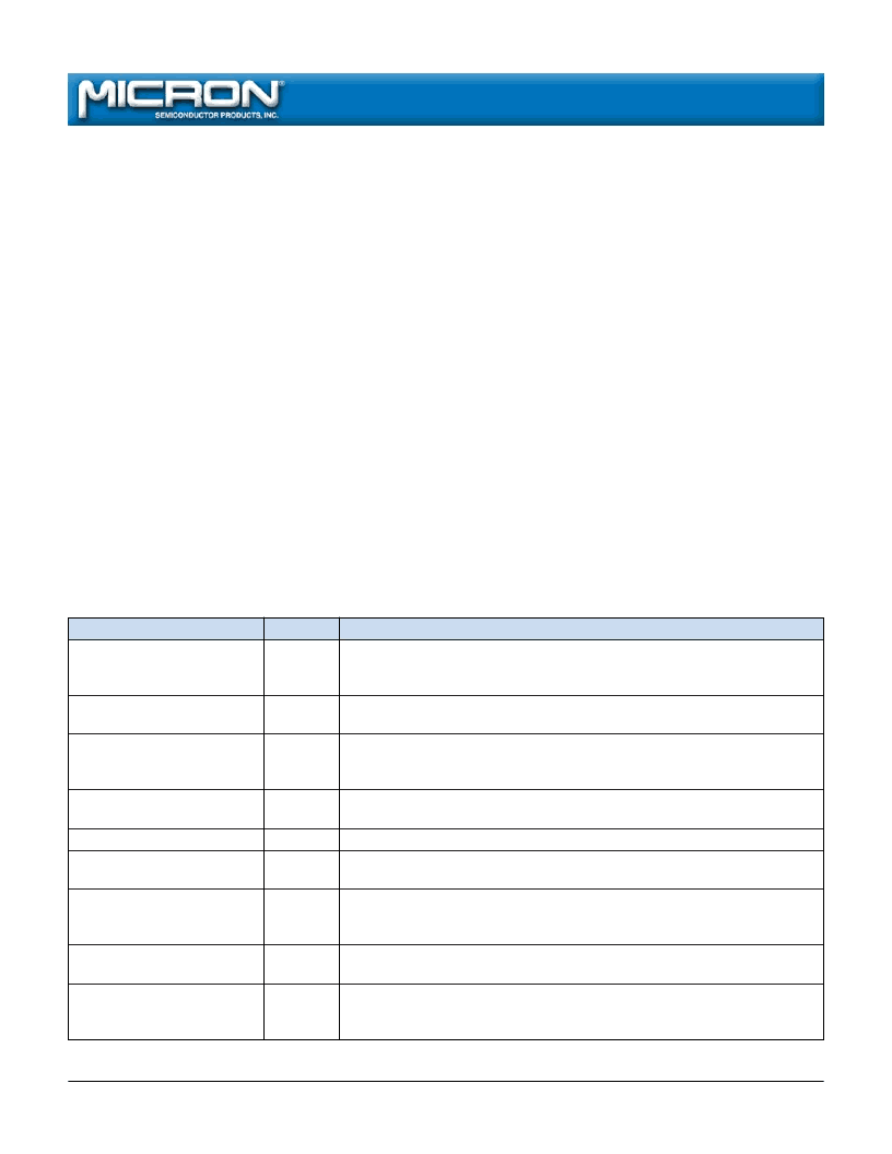
Table 1
Command Set
COMMAND
RESERVED
HEX CODE
00H
DESCRIPTION
This command and all unlisted commands are invalid and should not
be called. These commands are reserved to allow for future feature
enhancements.
Must be issued after any other command cycle before the array can be
read. It is not necessary to issue this command after power-up or RESET.
Allows the device ID and manufacturer compatibility ID to be read. A0 is
used to decode between the manufacturer compatibility ID (A0 = LOW)
and device ID (A0 = HIGH).
Allows the status register to be read. Please refer to Table 2 for more
information on the status register bits.
Clears status register bits 3-5, which cannot be cleared by the ISM.
The first command given in the two-cycle ERASE sequence. The ERASE will
not be completed unless followed by ERASE CONFIRM.
The second command given in the two-cycle ERASE sequence. Must follow
an ERASE SETUP command to be valid. Also used during an ERASE
SUSPEND to resume the ERASE.
The first command given in the two-cycle WRITE sequence. The write
data and address are given in the following cycle to complete the WRITE.
Requests a halt of the ERASE and puts the device into the erase suspend
mode. When the device is in this mode, only READ STATUS REGISTER,
READ ARRAY and ERASE RESUME commands may be executed.
READ ARRAY
FFH
IDENTIFY DEVICE
90H
READ STATUS REGISTER
70H
CLEAR STATUS REGISTER
ERASE SETUP
50H
20H
ERASE CONFIRM/RESUME
D0H
WRITE SETUP
40H or
10H
B0H
ERASE SUSPEND
相关PDF资料 |
PDF描述 |
|---|---|
| MT28F320A18 | FLASH MEMORY |
| MT2D18 | 1 Meg x 8 DRAM Module(5V,1M x 8 动态RAM模块) |
| MT46V16M4 | 4 Meg x 4 x 4 banks DDR SDRAM(4 M x 4 x 4组,双数据速率同步动态RAM) |
| MT46V4M16 | 1 Meg x 16 x 4 banks DDR SDRAM(1M x 16 x 4组,双数据速率同步动态RAM) |
| MT46V8M8 | 2 Meg x 8 x 4 banks DDR SDRAM(2 M x 8 x 4组,双数据速率同步动态RAM) |
相关代理商/技术参数 |
参数描述 |
|---|---|
| MT28F200B5SG-6 B | 制造商:Micron Technology Inc 功能描述:NOR Flash Parallel 5V 2Mbit 256K/128K x 8bit/16bit 60ns 44-Pin SOP Tray |
| MT28F200B5SG-6 T | 制造商:Micron Technology Inc 功能描述:NOR Flash Parallel 5V 2Mbit 256K/128K x 8bit/16bit 60ns 44-Pin SOP Tray |
| MT28F200B5SG-8 B TR | 制造商:Micron Technology Inc 功能描述:Flash Mem Parallel 5V 2M-Bit 256K x 8/128K x 16 80ns 44-Pin SOP T/R |
| MT28F320A18 | 制造商:MICRON 制造商全称:Micron Technology 功能描述:FLASH MEMORY |
| MT28F320J3 | 制造商:MICRON 制造商全称:Micron Technology 功能描述:Q-FLASHTM MEMORY |
发布紧急采购,3分钟左右您将得到回复。