- 您现在的位置:买卖IC网 > PDF目录69379 > ST7FMC2N6B6 (STMICROELECTRONICS) 8-BIT, FLASH, 8 MHz, MICROCONTROLLER, PDIP56 PDF资料下载
参数资料
| 型号: | ST7FMC2N6B6 |
| 厂商: | STMICROELECTRONICS |
| 元件分类: | 微控制器/微处理器 |
| 英文描述: | 8-BIT, FLASH, 8 MHz, MICROCONTROLLER, PDIP56 |
| 封装: | 0.600 INCH, PLASTIC, SDIP-56 |
| 文件页数: | 119/311页 |
| 文件大小: | 6511K |
| 代理商: | ST7FMC2N6B6 |
第1页第2页第3页第4页第5页第6页第7页第8页第9页第10页第11页第12页第13页第14页第15页第16页第17页第18页第19页第20页第21页第22页第23页第24页第25页第26页第27页第28页第29页第30页第31页第32页第33页第34页第35页第36页第37页第38页第39页第40页第41页第42页第43页第44页第45页第46页第47页第48页第49页第50页第51页第52页第53页第54页第55页第56页第57页第58页第59页第60页第61页第62页第63页第64页第65页第66页第67页第68页第69页第70页第71页第72页第73页第74页第75页第76页第77页第78页第79页第80页第81页第82页第83页第84页第85页第86页第87页第88页第89页第90页第91页第92页第93页第94页第95页第96页第97页第98页第99页第100页第101页第102页第103页第104页第105页第106页第107页第108页第109页第110页第111页第112页第113页第114页第115页第116页第117页第118页当前第119页第120页第121页第122页第123页第124页第125页第126页第127页第128页第129页第130页第131页第132页第133页第134页第135页第136页第137页第138页第139页第140页第141页第142页第143页第144页第145页第146页第147页第148页第149页第150页第151页第152页第153页第154页第155页第156页第157页第158页第159页第160页第161页第162页第163页第164页第165页第166页第167页第168页第169页第170页第171页第172页第173页第174页第175页第176页第177页第178页第179页第180页第181页第182页第183页第184页第185页第186页第187页第188页第189页第190页第191页第192页第193页第194页第195页第196页第197页第198页第199页第200页第201页第202页第203页第204页第205页第206页第207页第208页第209页第210页第211页第212页第213页第214页第215页第216页第217页第218页第219页第220页第221页第222页第223页第224页第225页第226页第227页第228页第229页第230页第231页第232页第233页第234页第235页第236页第237页第238页第239页第240页第241页第242页第243页第244页第245页第246页第247页第248页第249页第250页第251页第252页第253页第254页第255页第256页第257页第258页第259页第260页第261页第262页第263页第264页第265页第266页第267页第268页第269页第270页第271页第272页第273页第274页第275页第276页第277页第278页第279页第280页第281页第282页第283页第284页第285页第286页第287页第288页第289页第290页第291页第292页第293页第294页第295页第296页第297页第298页第299页第300页第301页第302页第303页第304页第305页第306页第307页第308页第309页第310页第311页
ST7MC1/ST7MC2
205/308
MOTOR CONTROLLER (Cont’d)
10.6.10.7 Timer Re-synchronisation
The 12-bit timer can be re-synchronized by a sim-
ple write access with FFh value in the MISR regis-
ter. Re-synchronization means that the 12-bit
counter is reset and all the compare preload regis-
ters MCP0, MCPU, MCPV, MCPW are transferred
to the active registers.
To re-synchronize the 12-bit timer properly , the
following procedure must be applied:
– 1. Load the new values in the preload compare
registers
– 2. Load FFh value in the MISR register (this will
reset the counter and transfer the compare
preload registers in the active registers: U event)
– 3. Reset the PUI flag by loading 7Fh in the MISR
register. Refer to Note 2 on page 208
Note: Loading FFh value in the MISR register will
have no effect on any other flag than the PUI flag
and will generate a PWM update interrupt if the
PUM bit is set.
Warning: In switched mode (SWA bit is reset), the
procedure is the same and loading FFh in the
MISR register will have no effect on flags except
on the PUI flag. As a consequence, it is recom-
mended to avoid setting RMI and RPI flags at the
same time in switched mode because none of
them will be taken into account.
10.6.10.8 PWM generator initialization and
start-up
The three-phase generator counter stays in reset
state (i.e. stopped and equal to 0), as long as MTC
peripheral clock is disabled (CKE = 0).
Setting the CKE bit has two actions on the PWM
generator:
■ It starts the PWM counter
■ It forces the update of all registers with preload
registers transferred on U update event, i.e.
MREP, MPCR, MCMP0, MCMPU, MCMPV,
MCMPW (in 12-bit mode, both MCMPxL and
MCMPxH must have been written, following the
mandatory LSB/MSB sequence, before setting
CKE bit). It consequently generates a U
interrupt.
10.6.11 Low Power Modes
Before executing a HALT or WFI instruction, soft-
ware must stop the motor, and may choose to put
the outputs in high impedance.
10.6.12 Interrupts
The MTC interrupt events are connected to the
three interrupt vectors (see Interrupts chapter).
They generate an interrupt if the corresponding
Enable Control Bit is set and the interrupt mask in
the CC register is reset (RIM instruction).
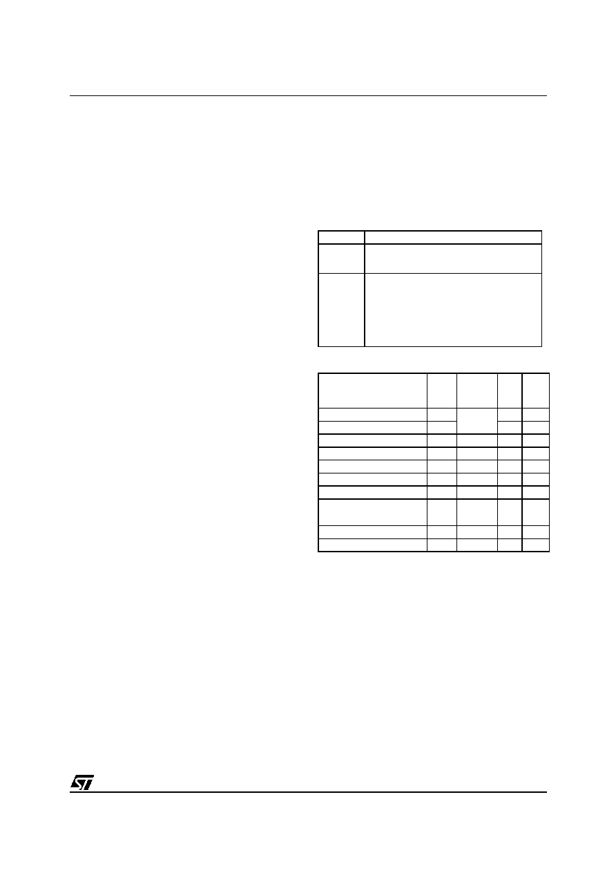
Mode
Description
WAIT
No effect on MTC interface.
MTC interrupts exit from Wait mode.
HALT
MTC registers are frozen.
In Halt mode, the MTC interface is in-
active. The MTC interface becomes
operational again when the MCU is
woken up by an interrupt with “exit
from Halt mode” capability.
Interrupt Event
Event
Flag
Enable
Control
Bit
Exit
from
Wait
Exit
from
Halt
Ratio increment
RPI
RIM
Yes
No
Ratio decrement
RMI
Yes
No
Speed Error
SEI
SEM
Yes
No
Emergency Stop
EI
EIM
Yes
No
Current Limitation
CLI
CLIM
Yes
No
BEMF Zero-Crossing
ZI
ZIM
Yes
No
End of Demagnetization
DI
DIM
Yes
No
Commutation or
Capture
CI
CIM
Yes
No
PWM Update
PUI
PUM
Yes
No
Sampling Out
SOI
SOM
Yes
Not
1
相关PDF资料 |
PDF描述 |
|---|---|
| ST7FMC2S6T6 | 8-BIT, FLASH, 8 MHz, MICROCONTROLLER, PQFP44 |
| ST7PMC2M9T6/XXX | 8-BIT, FLASH, 8 MHz, MICROCONTROLLER, PQFP80 |
| ST7PMC2R6T6/XXX | 8-BIT, FLASH, 8 MHz, MICROCONTROLLER, PQFP64 |
| ST7MC2N6B6 | MICROCONTROLLER, PDIP56 |
| ST7MC2M9T3 | MICROCONTROLLER, QFP80 |
相关代理商/技术参数 |
参数描述 |
|---|---|
| ST7FMC2N6T3 | 制造商:STMICROELECTRONICS 制造商全称:STMicroelectronics 功能描述:8-bit MCU with nested interrupts, Flash, 10-bit ADC, brushless motor control, five timers, SPI, LINSCI? |
| ST7FMC2N6T6 | 制造商:STMICROELECTRONICS 制造商全称:STMicroelectronics 功能描述:8-bit MCU with nested interrupts, Flash, 10-bit ADC, brushless motor control, five timers, SPI, LINSCI? |
| ST7FMC2N7B3 | 制造商:STMICROELECTRONICS 制造商全称:STMicroelectronics 功能描述:8-bit MCU with nested interrupts, Flash, 10-bit ADC, brushless motor control, five timers, SPI, LINSCI? |
| ST7FMC2N7B6 | 制造商:STMICROELECTRONICS 制造商全称:STMicroelectronics 功能描述:8-bit MCU with nested interrupts, Flash, 10-bit ADC, brushless motor control, five timers, SPI, LINSCI? |
| ST7FMC2N7T3 | 制造商:STMICROELECTRONICS 制造商全称:STMicroelectronics 功能描述:8-bit MCU with nested interrupts, Flash, 10-bit ADC, brushless motor control, five timers, SPI, LINSCI? |
发布紧急采购,3分钟左右您将得到回复。