- 您现在的位置:买卖IC网 > PDF目录69379 > ST7FMC2N6B6 (STMICROELECTRONICS) 8-BIT, FLASH, 8 MHz, MICROCONTROLLER, PDIP56 PDF资料下载
参数资料
| 型号: | ST7FMC2N6B6 |
| 厂商: | STMICROELECTRONICS |
| 元件分类: | 微控制器/微处理器 |
| 英文描述: | 8-BIT, FLASH, 8 MHz, MICROCONTROLLER, PDIP56 |
| 封装: | 0.600 INCH, PLASTIC, SDIP-56 |
| 文件页数: | 91/311页 |
| 文件大小: | 6511K |
| 代理商: | ST7FMC2N6B6 |
第1页第2页第3页第4页第5页第6页第7页第8页第9页第10页第11页第12页第13页第14页第15页第16页第17页第18页第19页第20页第21页第22页第23页第24页第25页第26页第27页第28页第29页第30页第31页第32页第33页第34页第35页第36页第37页第38页第39页第40页第41页第42页第43页第44页第45页第46页第47页第48页第49页第50页第51页第52页第53页第54页第55页第56页第57页第58页第59页第60页第61页第62页第63页第64页第65页第66页第67页第68页第69页第70页第71页第72页第73页第74页第75页第76页第77页第78页第79页第80页第81页第82页第83页第84页第85页第86页第87页第88页第89页第90页当前第91页第92页第93页第94页第95页第96页第97页第98页第99页第100页第101页第102页第103页第104页第105页第106页第107页第108页第109页第110页第111页第112页第113页第114页第115页第116页第117页第118页第119页第120页第121页第122页第123页第124页第125页第126页第127页第128页第129页第130页第131页第132页第133页第134页第135页第136页第137页第138页第139页第140页第141页第142页第143页第144页第145页第146页第147页第148页第149页第150页第151页第152页第153页第154页第155页第156页第157页第158页第159页第160页第161页第162页第163页第164页第165页第166页第167页第168页第169页第170页第171页第172页第173页第174页第175页第176页第177页第178页第179页第180页第181页第182页第183页第184页第185页第186页第187页第188页第189页第190页第191页第192页第193页第194页第195页第196页第197页第198页第199页第200页第201页第202页第203页第204页第205页第206页第207页第208页第209页第210页第211页第212页第213页第214页第215页第216页第217页第218页第219页第220页第221页第222页第223页第224页第225页第226页第227页第228页第229页第230页第231页第232页第233页第234页第235页第236页第237页第238页第239页第240页第241页第242页第243页第244页第245页第246页第247页第248页第249页第250页第251页第252页第253页第254页第255页第256页第257页第258页第259页第260页第261页第262页第263页第264页第265页第266页第267页第268页第269页第270页第271页第272页第273页第274页第275页第276页第277页第278页第279页第280页第281页第282页第283页第284页第285页第286页第287页第288页第289页第290页第291页第292页第293页第294页第295页第296页第297页第298页第299页第300页第301页第302页第303页第304页第305页第306页第307页第308页第309页第310页第311页
ST7MC1/ST7MC2
180/308
MOTOR CONTROLLER (Cont’d)
Hall sensors (or equivalent sensors providing posi-
tion information) are widely used for motor control.
There are two cases to be considered:
– BLDC motor or six-step synchronous motor
drive; “Sensor Mode” is recommended in this
case, as most tasks are performed by hardware
in the Delay Manager
– BLAC, asynchronous or motors supplied with 3-
phase sinewave-modulated PWM signals in gen-
eral; in this case “Speed Sensor Mode” allows
high accuracy speed measurement (the Sensor
Mode of the Delay Manager being unsuitable for
sinewave generation). Position information is
handled by software to lock the statoric field to
the rotoric one for driving synchronous motors.
Hall sensors are usually arranged in a 120° config-
uration. In that case they provide 3 ppr with both
rising and falling edge triggering; the tachogenera-
tor measurement method can therefore be ap-
plied. The main difference lies in the fact that one
must use the position information they provide.
This can be done using the three MCIx pins and
the analog multiplexer to know which of the 3 sen-
sors toggled; an interrupt is generated just after
the expected transition (refer to Figure 101).
As described in Figure 102, the MTIM Timer is re-
configured depending on the selected sensor. This
means that most of Delay Manager registers are
used for a different purpose, with modified func-
tionalities.
For greater precision, the MTIM Up-counter is ex-
tended to 16 bits using MTIM and an additional
MTIML register. On a capture event, the current
counter value is captured and the counter
[MTIM:MTIML] is cleared. The counting direction
is not affected by the EDIR bit when using an en-
coder sensor.
A 16-bit capture register is used to store the cap-
tured value of the extended MTIM counter: the
speed result will be either a period in clock cycles
or a number of encoder pulses. This 16-bit register
is mapped in the MZREG and MZPRV register ad-
dresses. To ensure that the read value is not cor-
rupted between the high and low byte accesses, a
read access to the MSB of this register (MZREG)
locks the LSB (ie MZPRV content is locked) until it
is read and any other capture event in between
these two accesses is discarded.
A compare unit allows a maximum value to be en-
tered for the tacho periods. If the 16-bit counter
[MTIM:MTIML] exceeds this value, a Speed Error
interrupt is generated. This may be used to warn
the user that the tachogenerator signal is lost
(wires disconnected, motor stalled,...). As 8-bit ac-
curacy is sufficient for this purpose, only the MS-
Byte of the counter (i.e. MTIM) is compared to 8-bit
compare register, mapped in the MDREG register
location. The LSByte is nevertheless compared
with a fixed FFh value. Available values for com-
parison are therefore FFFFh, FEFFh, FDFFh, ...,
01FFh, 00FFh.
Note: This functionality is not useful when using
an encoder. With an encoder, user must monitor
the captured values by software during the period-
ic capture interrupts: for instance, when driving an
AC motor, if the values are too low compared to
the stator frequency, a software interrupt may be
triggered.
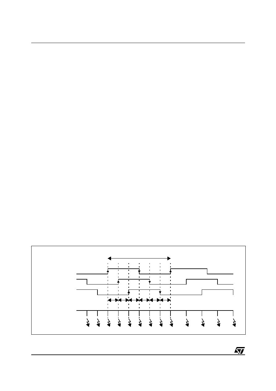
Figure 101. Hall sensor period acquisition using MTIM timer
1 mechanical cycle
MCIA: Hall Sensor 1
MCIB: Hall Sensor 2
MCIC: Hall Sensor 3
Tacho Capture
Period measurements
C
Interrupts
1-2
3-1
2-3
3-1
1-2
2-3
1
相关PDF资料 |
PDF描述 |
|---|---|
| ST7FMC2S6T6 | 8-BIT, FLASH, 8 MHz, MICROCONTROLLER, PQFP44 |
| ST7PMC2M9T6/XXX | 8-BIT, FLASH, 8 MHz, MICROCONTROLLER, PQFP80 |
| ST7PMC2R6T6/XXX | 8-BIT, FLASH, 8 MHz, MICROCONTROLLER, PQFP64 |
| ST7MC2N6B6 | MICROCONTROLLER, PDIP56 |
| ST7MC2M9T3 | MICROCONTROLLER, QFP80 |
相关代理商/技术参数 |
参数描述 |
|---|---|
| ST7FMC2N6T3 | 制造商:STMICROELECTRONICS 制造商全称:STMicroelectronics 功能描述:8-bit MCU with nested interrupts, Flash, 10-bit ADC, brushless motor control, five timers, SPI, LINSCI? |
| ST7FMC2N6T6 | 制造商:STMICROELECTRONICS 制造商全称:STMicroelectronics 功能描述:8-bit MCU with nested interrupts, Flash, 10-bit ADC, brushless motor control, five timers, SPI, LINSCI? |
| ST7FMC2N7B3 | 制造商:STMICROELECTRONICS 制造商全称:STMicroelectronics 功能描述:8-bit MCU with nested interrupts, Flash, 10-bit ADC, brushless motor control, five timers, SPI, LINSCI? |
| ST7FMC2N7B6 | 制造商:STMICROELECTRONICS 制造商全称:STMicroelectronics 功能描述:8-bit MCU with nested interrupts, Flash, 10-bit ADC, brushless motor control, five timers, SPI, LINSCI? |
| ST7FMC2N7T3 | 制造商:STMICROELECTRONICS 制造商全称:STMicroelectronics 功能描述:8-bit MCU with nested interrupts, Flash, 10-bit ADC, brushless motor control, five timers, SPI, LINSCI? |
发布紧急采购,3分钟左右您将得到回复。