- 您现在的位置:买卖IC网 > PDF目录69378 > ST7PLITEUS5U3TR (STMICROELECTRONICS) 8-BIT, FLASH, 8 MHz, MICROCONTROLLER, DSO8 PDF资料下载
参数资料
| 型号: | ST7PLITEUS5U3TR |
| 厂商: | STMICROELECTRONICS |
| 元件分类: | 微控制器/微处理器 |
| 英文描述: | 8-BIT, FLASH, 8 MHz, MICROCONTROLLER, DSO8 |
| 封装: | LEAD FREE, DFN-8 |
| 文件页数: | 38/108页 |
| 文件大小: | 1957K |
| 代理商: | ST7PLITEUS5U3TR |
第1页第2页第3页第4页第5页第6页第7页第8页第9页第10页第11页第12页第13页第14页第15页第16页第17页第18页第19页第20页第21页第22页第23页第24页第25页第26页第27页第28页第29页第30页第31页第32页第33页第34页第35页第36页第37页当前第38页第39页第40页第41页第42页第43页第44页第45页第46页第47页第48页第49页第50页第51页第52页第53页第54页第55页第56页第57页第58页第59页第60页第61页第62页第63页第64页第65页第66页第67页第68页第69页第70页第71页第72页第73页第74页第75页第76页第77页第78页第79页第80页第81页第82页第83页第84页第85页第86页第87页第88页第89页第90页第91页第92页第93页第94页第95页第96页第97页第98页第99页第100页第101页第102页第103页第104页第105页第106页第107页第108页
ST7LITEUSx
35/108
POWER SAVING MODES (Cont’d)
8.4 ACTIVE-HALT AND HALT MODES
ACTIVE-HALT and HALT modes are the two low-
est power consumption modes of the MCU. They
are both entered by executing the ‘HALT’ instruc-
tion. The decision to enter either in ACTIVE-HALT
or HALT mode is given by the LTCSR/ATCSR reg-
ister status as shown in the following table:.
8.4.1 ACTIVE-HALT MODE
ACTIVE-HALT mode is the lowest power con-
sumption mode of the MCU with a real time clock
available. It is entered by executing the ‘HALT’ in-
struction when active halt mode is enabled.
The MCU can exit ACTIVE-HALT mode on recep-
tion of a Lite Timer / AT Timer interrupt or a RE-
SET.
– When exiting ACTIVE-HALT mode by means of
a RESET, a 64 CPU cycle delay occurs. After the
start up delay, the CPU resumes operation by
fetching the reset vector which woke it up (see
– When exiting ACTIVE-HALT mode by means of
an interrupt, the CPU immediately resumes oper-
ation by servicing the interrupt vector which woke
it up (see Figure 22).
When entering ACTIVE-HALT mode, the I bit in
the CC register is cleared to enable interrupts.
Therefore, if an interrupt is pending, the MCU
wakes up immediately.
In ACTIVE-HALT mode, only the main oscillator
and the selected timer counter (LT/AT) are running
to keep a wake-up time base. All other peripherals
are not clocked except those which get their clock
supply from another clock generator (such as ex-
ternal or auxiliary oscillator).
Caution: As soon as ACTIVE-HALT is enabled,
executing a HALT instruction while the Watchdog
is active does not generate a RESET if the
WDGHALT bit is reset.
This means that the device cannot spend more
than a defined delay in this power saving mode.
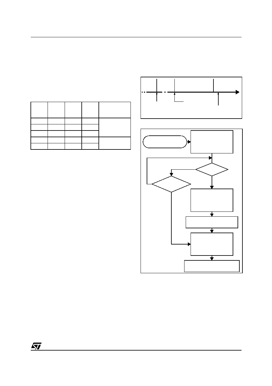
Figure 21. ACTIVE-HALT Timing Overview
Figure 22. ACTIVE-HALT Mode Flow-chart
Notes:
1. This delay occurs only if the MCU exits ACTIVE-
HALT mode by means of a RESET.
2. Peripherals clocked with an external clock
source can still be active.
3. Only the Lite Timer RTC and AT Timer interrupts
can exit the MCU from ACTIVE-HALT mode.
4. Before servicing an interrupt, the CC register is
pushed on the stack. The I bit of the CC register is
set during the interrupt routine and cleared when
the CC register is popped.
LTCSR
TBIE bit
ATCSR
OVFIE
bit
ATCSR
CK1 bit
ATCSR
CK0 bit
Meaning
0x
x
0
ACTIVE-HALT
mode disabled
00
x
01
11
1
xxx
ACTIVE-HALT
mode enabled
x1
0
1
HALT
RUN
64 CPU
CYCLE DELAY 1)
RESET
OR
INTERRUPT
HALT
INSTRUCTION
FETCH
VECTOR
ACTIVE
[Active Halt Enabled]
HALT INSTRUCTION
RESET
INTERRUPT 3)
Y
N
Y
CPU
OSCILLATOR
PERIPHERALS 2)
IBIT
ON
OFF
0
OFF
FETCH RESET VECTOR
OR SERVICE INTERRUPT
CPU
OSCILLATOR
PERIPHERALS 2)
IBIT
ON
OFF
X 4)
ON
CPU
OSCILLATOR
PERIPHERALS
IBITS
ON
X 4)
ON
64 CPU CLOCK CYCLE
DELAY
(Active Halt enabled)
1
相关PDF资料 |
PDF描述 |
|---|---|
| ST7PLITEUS5M6TR | 8-BIT, MROM, 8 MHz, MICROCONTROLLER, PDSO8 |
| ST7PLITEUS5M6 | 8-BIT, MROM, 8 MHz, MICROCONTROLLER, PDSO8 |
| ST7FLITEUS5M3TR | 8-BIT, FLASH, 8 MHz, MICROCONTROLLER, PDSO8 |
| ST7FLITEUS2B3 | 8-BIT, FLASH, 8 MHz, MICROCONTROLLER, PDIP8 |
| ST7FSCR1E4U1 | 8-BIT, FLASH, 8 MHz, MICROCONTROLLER, QCC64 |
相关代理商/技术参数 |
参数描述 |
|---|---|
| ST7PLITEUS5U6 | 制造商:STMICROELECTRONICS 制造商全称:STMicroelectronics 功能描述:8-bit MCU with single voltage Flash memory, ADC, timers |
| ST7PLITEUS5U6TR | 制造商:STMICROELECTRONICS 制造商全称:STMicroelectronics 功能描述:8-bit MCU with single voltage Flash memory, ADC, timers |
| ST7PMC1K2B3 | 制造商:STMICROELECTRONICS 制造商全称:STMicroelectronics 功能描述:8-bit MCU with nested interrupts, Flash, 10-bit ADC, brushless motor control, five timers, SPI, LINSCI? |
| ST7PMC1K2B6 | 制造商:STMICROELECTRONICS 制造商全称:STMicroelectronics 功能描述:8-BIT MCU WITH NESTED INTERRUPTS, FLASH, 10-BIT ADC, BRUSHLESS MOTOR CONTROL, FIVE TIMERS, SPI, LINSCI |
| ST7PMC1K2T3 | 制造商:STMICROELECTRONICS 制造商全称:STMicroelectronics 功能描述:8-bit MCU with nested interrupts, Flash, 10-bit ADC, brushless motor control, five timers, SPI, LINSCI? |
发布紧急采购,3分钟左右您将得到回复。